Modern houses, regardless of the material used in their construction, need to be designed and costed. It is at this stage that the characteristics are calculated for building heating systems. In those schemes where ordinary water circulates, the amount of coolant is calculated based on the thermal load of the entire building.
This indicator is necessary for accurately selecting the tank capacity intended for pressure regulation. This parameter is directly related to the design load of the heating system of a private building. Properly selected equipment used for heating a residential building will normally cope with the main task - creating a comfortable temperature regime in residential and auxiliary premises.
Table with standard indicators for residential premises Source stroypol14.ru
When performing a calculation, an exact expression is required that gives the correct result for choosing a boiler.
Calculated coolant flow through the heating device formula
The estimated consumption of network water for a heating system (t/h), connected according to a dependent circuit, can be determined using the formula:
Formula 1. Estimated consumption of network water for CO
where Qо.р. is the design load on the heating system, Gcal/h;
τ1.р. - water temperature in the supply pipeline of the heating network at the design temperature of the outside air for heating design, ° C;
τ2.р. - water temperature in the return pipeline of the heating system at the design temperature of the outside air for heating design, °C;
The estimated water flow in the heating system is determined from the expression:
Formula 2. Estimated water flow in the heating system
τ3.р. - water temperature in the supply pipeline of the heating system at the design temperature of the outside air for heating design, ° C;
Relative consumption of network water Grel. for the heating system:
Formula 3. Relative consumption of network water for CO
where Gc. is the current value of network consumption for the heating system, t/h.
Relative heat consumption Qrel. for the heating system:
Formula 4. Relative heat consumption for CO
where Qо. is the current value of heat consumption for the heating system, Gcal/h
where Qо.р. is the calculated value of heat consumption for the heating system, Gcal/h
Estimated coolant flow in a heating system connected according to an independent circuit:
Formula 5. Estimated CO consumption according to an independent scheme
where: t1.р, t2.р. - design temperature of the heated coolant (second circuit), respectively, at the outlet and inlet of the heat exchanger, ºС;
The estimated coolant flow in the ventilation system is determined by the formula:
Formula 6. Estimated consumption for SW
where: Qv.r. - design load on the ventilation system Gcal/h;
τ2.v.r. - calculated temperature of the network water after the ventilation system heater, ºС.
The estimated coolant flow for the hot water supply system (DHW) for open heating systems is determined by the formula:
Formula 7. Estimated consumption for open hot water systems
In the adjustment calculation for closed DHW circuits, the load is determined as the value of the Average DHW load field multiplied by the value of the Closed Balance Factor field. hot water
The balance factor allows the user to adjust the amount of load (and flow) for which adjustment is made. If the field value is not specified, then the default coefficient value is used in the calculation:
Table 17. Balance coefficient. DHW (default values)
Source
Pressure loss at local resistances
Local resistance on a pipe section is the resistance on fittings, fittings, equipment, etc. Pressure losses at local resistances are calculated using the formula :
where Δpm.s. — pressure loss at local resistances, Pa;
Σξ is the sum of local resistance coefficients on the site; local resistance coefficients are indicated by the manufacturer for each fitting
V is the coolant velocity in the pipeline, m/s;
ρ—coolant density, kg/m3.
Features of selecting a circulation pump
The pump is selected according to two criteria:
- The amount of pumped liquid, expressed in cubic meters per hour (m³/h).
- Pressure expressed in meters (m).
With pressure, everything is more or less clear - this is the height to which the liquid must be raised and is measured from the lowest to the highest point or to the next pump, if the project provides more than one.
Expansion tank volume
Everyone knows that liquid tends to increase in volume when heated. To prevent the heating system from looking like a bomb and leaking at all the seams, there is an expansion tank into which the displaced water from the system is collected.
What size tank should I purchase or make?
Everything is simple, knowing the physical characteristics of water.
Let's talk about the amount of pumped liquid in more detail.
Water consumption in the heating system is calculated using the formula:
- G – water consumption in the heating system, kg/sec;
- Q – amount of heat compensating for heat loss, W;
- c is the specific heat capacity of water, this value is known and equal to 4200 J/kg*ᵒC (note that any other coolants have worse performance compared to water);
- t2 – temperature of the coolant entering the system, ᵒС;
- t1 – coolant temperature at the outlet of the system, ᵒС;
The result of this formula will give the coolant consumption per second of time to replenish heat loss, then this indicator is converted into hours.
Let's consider the indicator the calculated amount of heat required to compensate for heat losses.
Perhaps this is the most complex and important criterion, requiring engineering knowledge, which must be approached responsibly.
If this is a private house, then the indicator can vary from 10-15 W/m² (such indicators are typical for “passive houses”) to 200 W/m² or more (if it is a thin wall with no or insufficient insulation).
In practice, construction and trade organizations take the heat loss indicator as a basis - 100 W/m².
We multiply the calculated loss figure by the area of the house and then substitute it into the water consumption formula.
Results of hydraulic calculations
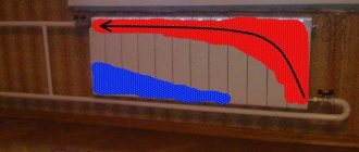
As a result, it is necessary to sum up the resistance of all sections up to each radiator and compare with the control values. In order for the pump built into the gas boiler to provide heat to all radiators, the pressure loss on the longest branch should not exceed 20,000 Pa. The coolant movement speed in any area should be in the range of 0.25 - 1.5 m/s. At a speed above 1.5 m/s, noise may appear in the pipes, and a minimum speed of 0.25 m/s is recommended according to SNiP 2.04.05-91 to avoid airing of the pipes.
In order to withstand the above conditions, it is enough to select the correct pipe diameters. This can be done using the table.
| Pipe | Minimum power, kW | Maximum power, kW |
| Metal-plastic pipe 16 mm | 2,8 | 4,5 |
| Metal-plastic pipe 20 mm | 5 | 8 |
| Metal-plastic pipe 26 mm | 8 | 13 |
| Metal-plastic pipe 32 mm | 13 | 21 |
| Polypropylene pipe 20 mm | 4 | 7 |
| Polypropylene pipe 25 mm | 6 | 11 |
| Polypropylene pipe 32 mm | 10 | 18 |
| Polypropylene pipe 40 mm | 16 | 28 |
It indicates the total power of the radiators that the pipe provides heat.
Features of calculations for an apartment building
There are two options for arranging heating for an apartment building:
- Common boiler room for the whole house.
- Individual heating for each apartment.
The peculiarity of the first option is that the project is done without taking into account the personal wishes of the residents of individual apartments.
For example, if in one separate apartment they decide to install a “warm floor” system, and the input temperature of the coolant is 70-90 degrees with the permissible temperature for pipes up to 60 ᵒC. Or, conversely, if the whole house decides to have heated floors, one individual subject may end up in a cold apartment if he installs conventional radiators. Calculation of water consumption in the heating system follows the same principle as for a private house.
Among the advantages of individual heating in your apartment, you need to highlight the moment when you can install the type of heating system that you consider a priority for yourself.
When calculating water consumption, you should add 10% for thermal energy, which will be used for heating staircases and other engineering structures.
Preliminary preparation of water for a future heating system is of great importance. It determines how efficiently heat exchange will occur. Of course, distillate would be the ideal option, but we do not live in an ideal world.
Although, many today use distilled water for heating. Read about this in the article.
In fact, the water hardness indicator should be 7-10 mEq/1L. If this figure is higher, it means that the water in the heating system needs to be softened. Otherwise, the process of sedimentation of magnesium and calcium salts in the form of scale occurs, which will lead to rapid wear of the system components.
The most affordable way to soften water is boiling, but, of course, this is not a panacea and does not completely solve the problem.
You can use magnetic softeners. This is a fairly affordable and democratic approach, but it works when heated no higher than 70 degrees.
There is a principle of water softening, so-called inhibitor filters, based on several reagents. Their task is to purify water from lime, soda ash, and sodium hydroxide.
I would like to believe that this information was useful to you. We will be grateful if you press the social media buttons.
Accurate calculation of heat loss
Using a special value that characterizes heat flow and is measured in kcal/hour, the heat loss of a house is determined.
This value shows how much heat is lost through the walls of the building at a certain temperature condition inside the house.
This indicator is considered in direct dependence on the architectural features of the building, the building materials from which it is constructed, the thickness and degree of thermal insulation of the walls, ceiling and floor. The glazing area, the quality of heat insulators and adherence to technology during their installation are influenced.
That is, heat loss consists of many elements.
The formula is as follows: G = Sх1/Pох(Тв-Тн)к, where:
- G is the value expressed in kcal/h;
- Po is an indicator of resistance to heat transfer;
- Тв иТн - difference in temperature conditions inside and outside;
- k is a coefficient that shows how much heat is lost; it is different for each barrier.
Since the temperature outside and indoors changes during the heating season, the values are taken as average. The fact that each region with different climatic conditions has its own indicator is also taken into account.
This formula uses specific quantities, all of which are known. Using it you can find out the heat losses of any building.
The reduction factor and resistance value Po belong to the category of normative and reference information.
For example, the following coefficients may be needed:
- 1 - if there is soil or wooden logs under the finished floors;
- 0.9 - for attic floors, where the roofing material is steel, tiles on sheathing, asbestos cement (or a roof without an attic with ventilation);
- 0.8 - the roofing materials are the same, but the flooring is solid;
- 0.75 - attic floors, where the roof is made of any rolled material;
- 0.7 - for internal walls that open into an adjacent unheated room without external walls;
- 0.4 - for internal walls that connect to an adjacent unheated room that has external walls, and for floors above a cellar deepened into the ground;
- 0.75 - floors above the cellar, located above the ground;
- 0.6 - surfaces above basements located either below the ground or no higher than one meter above it.
- Similarly, you can select coefficients for other situations.
On a note. When choosing a house project, it is good to think through in advance the options for how to ensure that the perimeter of the external cold walls is minimal. There is a direct relationship: the larger the area of the external walls, the higher the heat loss. Houses with a lot of protruding elements lose a lot of heat.
The following resistance values may be needed:
- 0.38 - with solid brickwork with a wall thickness of 13.5 cm, 0.57 - with a masonry thickness of 26.5 cm, 0.76 - 39.5 cm, 0.94 - 52.5 cm, 1.13 - 65.5 cm.
- 0.9 - with continuous masonry with an air gap with a thickness of 43.5 cm, 1.09 - 56.5 cm, 1.28 - 65.5 cm;
- 0.89 - with continuous masonry of decorative bricks with a thickness of 39.5 cm, 1.2 - 52.5 cm, 1.4 - 65.5 cm.
- 1.03 - for solid masonry, where the thermal insulation layer is 39.5 cm thick, 1.49 - 52.5 cm;
- 1.33 - for wooden walls made of wood (not timber) with a thickness of 200 mm, 1.45 - 220 mm, 1.56 - 240 mm;
- 1.18 - for walls made of timber with a thickness of 150 mm, 1.28 - 180 mm, 1.32 - 200 mm;
- 0.69 - for attic floors made of reinforced concrete slabs with insulation with a thickness of 100 mm, 0.89 - 150 mm.
These indicators are taken for the formula for water consumption for heating.
Selecting a circulation pump for a heating system. Part 2
The circulation pump is selected based on two main characteristics:
G* - flow rate, expressed in m 3 / hour;
H - pressure expressed in m.
*To record coolant flow, manufacturers of pumping equipment use the letter Q. Manufacturers of shut-off valves, for example, Danfoss, use the letter G to calculate flow. In domestic practice, this letter is also used. Therefore, within the framework of the explanations of this article, we will also use the letter G. But in other articles, going directly to the analysis of the pump operation schedule, we will still use the letter Q for flow rate.
Converting the result to normal form
It is worth noting that in practice you will not find such water consumption anywhere. All water pump manufacturers express pump power in cubic meters per hour.
Some transformations should be made, recalling the school physics course. So, 1 kg of water, that is, coolant, is 1 cubic meter. dm of water. To find out how much one cubic meter of coolant weighs, you need to find out how many cubic decimeters there are in one cubic meter.
Using some simple calculations or simply using tabular data, we find that one cubic meter contains 1000 cubic decimeters. This means that one cubic meter of coolant will have a mass of 1000 kg.
Then in one second it is necessary to pump water with a volume of 2.4/1000 = 0.0024 cubic meters. m.
Now all that remains is to convert the seconds to hours. Knowing that there are 3600 seconds in one hour, we find that in one hour the pump must pump 0.0024*3600 = 8.64 cubic meters per hour.
Determining the flow rate (G, m 3 / hour) of the coolant when choosing a pump
The starting point for selecting a pump is the amount of heat that the house loses. How to find out? To do this, you need to calculate heat loss.
This is a complex engineering calculation that requires knowledge of many components. Therefore, in this article we will omit this explanation, and as a basis for the amount of heat loss we will take one of the common (but far from accurate) methods used by many installation companies.
Its essence lies in a certain average loss per 1 m 2. This value is arbitrary and amounts to 100 W/m2 (if a house or room has uninsulated brick walls, and even those of insufficient thickness, the amount of heat lost by the room will be significantly greater. And vice versa, if the enclosing structures of the house are made using modern materials and have good thermal insulation, heat loss will be reduced and can be 90 or 80 W/m2).
So, let's say you have a house with an area of 120 or 200 m2. Then the amount of heat loss we have agreed upon for the entire house will be:
120 * 100 = 12000 W or 12 kW.
What does this have to do with the pump? The most direct.
The process of heat loss in the house occurs constantly, which means that the process of heating the premises (compensation for heat loss) must be ongoing.
Imagine that you have no pump, no pipelines. How would you solve this problem?
To compensate for heat loss, you would have to burn some type of fuel in a heated room, for example, firewood, which is basically what people have been doing for thousands of years.
Quick selection of pipe diameters from the table
For houses up to 250 sq.m. provided that there is a 6-piece pump and radiator thermal valves, you don’t have to do a full hydraulic calculation. You can select the diameters from the table below. On short sections you can slightly exceed the power. Calculations were made for coolant Δt=10oC and v=0.5m/s.
| Pipe | Radiator power, kW |
| Pipe 14x2 mm | 1.6 |
| Pipe 16x2 mm | 2,4 |
| Pipe 16x2.2 mm | 2,2 |
| Pipe 18x2 mm | 3,23 |
| Pipe 20x2 mm | 4,2 |
| Pipe 20x2.8 mm | 3,4 |
| Pipe 25x3.5 mm | 5,3 |
| Pipe 26x3 mm | 6,6 |
| Pipe 32x3 mm | 11,1 |
| Pipe 32x4.4 mm | 8,9 |
| Pipe 40x5.5 mm | 13,8 |
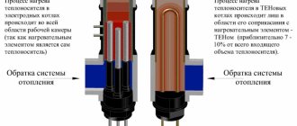
Requirements for coolant in the heating system
There are 5 points that must be observed:
- high heat transfer rate;
- low viscosity , with standard (like water) fluidity;
- low expansion when cooling ;
- no toxicity ;
- low cost.
Photo 1. Eco-30 coolant based on propylene glycol, weight 20 kg, .
To make a choice, it is recommended to contact a professional plumber who will help you make calculations and select the appropriate coolant.
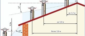
Heat supply standards RF PP 354 dated 05/06/2011 and GOST
On May 6, 2011, a Government Order was issued, which is still in effect today. Based on it, the heating period is determined not so much by the period of the year, but by the ambient temperature outside.
The main heating begins to work under the conditions that the external thermometer shows a mark below 8 ° C, and the cold snap continues for at least several days.
On the sixth day, the pipes already begin to heat the rooms. If warming occurs within the specified time, the heating period is postponed. In all parts of the country, radiators bring joy with their own warmth from mid-autumn and maintain optimal temperatures until the end of April.
If frost has set in and the pipes remain cold, this may be the result of a breakdown in the system. In the event of a global malfunction or unfinished repair work, you will need to use an additional heating device until the breakdown is fixed.
If the difficulty lies in air pockets filling the batteries, then contact the operating company. Within 24 hours after submitting the application, a plumber assigned to the house will arrive and “blow out” the problematic area.
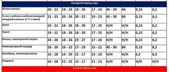
The standard and norms for possible values of ambient temperature are specified in the document “GOST R 51617-200. Housing and communal services. General technical information". The range of air heating in the apartment can vary from 10 to 25 °C, depending on the purpose of each room that is heated.
- Living rooms, which include guest rooms, sleeping rooms, offices and similar, must be heated to 22 °C. This mark may fluctuate up to 20 °C, especially in cold corner rooms. The maximum thermometer value should not exceed 24 °C.
A temperature of 19 to 21 °C is considered suitable, but zone cooling to 18 °C or active heating to 26 °C is permitted.
- The bathroom follows the temperature range of the kitchen. But, the room where the bathtub is installed, or the adjacent plumbing unit, are considered rooms with a very high level of moisture. This part of the living space can heat up to 26 °C and cool down to 18 °C. Although, even at an acceptable permissible value of 20 °C, it is uncomfortable to use the bathroom for its intended purpose.
- A comfortable temperature range for corridors is 18–20 °C. But, reducing the mark to 16 °C is considered quite tolerable.
- Indicators in pantries may be even lower. While 16 to 18°C is a good range, the 12 or 22°C mark is not out of line.
- Upon entering the entrance, a resident of the house has the right to hope for an air temperature of at least 16 °C.
- A person spends only a short time in the elevator, hence the comfortable temperature of only 5 °C.
- The coldest places in high-rise buildings are the basement and attic floor. The temperature here can drop to 4 °C.
Home warmth also depends on the time of day. It is officially recognized that during sleep a person needs a small amount of heat. Based on this, a decrease in temperature in the premises by 3 degrees from 00.00 to 05.00 in the morning is not considered a violation.
How to calculate consumption
The value represents the amount of coolant in kilograms that is consumed per second . It is used to transfer temperature to the room through radiators. To calculate, you need to know the boiler consumption, which is spent on heating one liter of water.
G = N / Q , where:
- N - boiler power, W.
- Q —heat, J/kg.
The value is converted to kg/hour, multiplied by 3600.
Formula for calculating the required volume of liquid
Refilling of pipes is required after repair or reconstruction of the piping. To do this, find the amount of water needed by the system.
Usually it is enough to collect your passport data and add it up. But you can also find it manually. To do this, consider the length and cross-section of the pipes.
The numbers are multiplied and added to the batteries. The volume of radiator sections is:
- Aluminum, steel or alloy - 0.45 l.
- Cast iron - 1.45 l.
There is also a formula that can be used to approximately determine the total amount of water in the harness:
V = N * VkW , where:
- N - boiler power, W.
- VkW is the volume that is sufficient to transfer one kilowatt of heat, dm 3.
This allows you to calculate only an approximate number, so it is better to check the documents.
To get a complete picture, you also need to calculate the volume of water held by other components of the piping: expansion tank, pump, etc.
Attention! The tank is especially important : it compensates for the pressure that increases due to the expansion of the liquid when heated.
First of all, you need to decide on the substance used:
- water has an expansion coefficient of 4%;
V = (Vs * E)/D , where:
- E is the expansion coefficient of the liquid as stated above.
- Vs is the estimated flow rate of the entire piping, m3.
- D is the efficiency of the tank, indicated in the device passport.
Having found these values, they need to be summed. Typically, four volume indicators are obtained: pipes, radiators, heater and tank.
Using the data obtained, you can create a heating system and fill it with water. The filling process depends on the scheme:
- “Gravity flow” is performed from the highest point of the pipeline: a funnel is inserted and liquid is released. This is done slowly and evenly. First, open the tap below and place the container. This helps avoid the formation of air pockets. Used if there is no forced current.
- Forced - requires a pump. Any one will do, although it is better to use a circulation one, which is then used for heating. During the process, you need to take readings from the pressure gauge to avoid increasing pressure. And also be sure to open the air valves, which helps with the release of gas.
How to calculate the minimum coolant flow
They are also calculated as the liquid consumption per hour for heating the premises.
It is found during the break between heating seasons as a number that depends on the hot water supply. There are two formulas used in calculations.
If there is no forced circulation of hot water in the system, or it is turned off due to frequency of operation, then the calculation is performed taking into account the average flow rate:
Qgsr is the average value of heat that the system transfers per hour of operation during the non-heating season, J.
$ is the coefficient of change in water consumption in summer and winter. 0.8 or 1.0 respectively .
Tp - supply temperature.
Tob3 - in the return when the heater is connected in parallel.
C is the heat capacity of water, taken equal to 10 -3, J/°C.
Temperatures are taken equal to 70 and 30 degrees Celsius, respectively.
If there is forced DHW circulation or taking into account water heating at night:
Qtsg is the heat consumption for heating the liquid, J.
The value of this indicator is taken equal to (Ktp * Qgsr) / (1 + Ktp), where Ktp is the coefficient of heat loss by pipes, and Qgsr is the average power consumption for water per hour.
Tp - supply temperature.
Tob6 - return measured after the boiler circulating liquid through the system. It is equal to five plus the minimum allowable at the point of water collection.
Experts take the numerical value of the coefficient Ktp from the following table:
| Types of DHW systems | Loss of water by coolant | |
| Taking into account heating networks | Without them | |
| With insulated risers | 0,15 | 0,1 |
| Insulated and with towel rails | 0,25 | 0,2 |
| Without insulation, but with dryers | 0,35 | 0,3 |
Important! The calculation of the minimum flow rate can be found in more detail in building codes and regulations 2.04.01-85.
How to find out heat loss
To find out the heat loss of a house in quantitative terms, there is a special formula. With its help, the power of thermal radiation into the external environment of each square meter of wall area, floor surfaces and ceiling is calculated.
The average values are as follows:
- 100 Watt per 1 sq. meter of area for ordinary brick walls with standard interior decoration;
- more than 100 watts for poorly insulated walls;
- 80 Watt for floors with external and internal thermal insulation and modern double-glazed windows.
In order to derive these indicators, use a formula or table data.
On a note. Walls, attics and basements are sometimes not insulated correctly, and a large amount of heat-insulating materials is wasted. According to the rules, they are insulated not from the inside, but from the outside, in order to avoid the accumulation of condensation, which worsens the thermal characteristics of the building.
For example, a project for a one-story house of 100 m²
To clearly explain all the methods for determining the amount of thermal energy, we suggest taking as an example a one-story house with a total area of 100 square meters (according to external measurements), shown in the drawing. Let us list the technical characteristics of the building:
- region of construction – temperate climate zone (Minsk, Moscow);
- thickness of external fences – 38 cm, material – sand-lime brick;
- external wall insulation – foam plastic 100 mm thick, density – 25 kg/m³;
- floors – concrete on the ground, no basement;
- ceiling - reinforced concrete slabs, insulated on the cold attic side with 10 cm foam plastic;
- windows – standard metal-plastic with 2 glasses, size – 1500 x 1570 mm (h);
- the entrance door is metal 100 x 200 cm, insulated from the inside with 20 mm extruded polystyrene foam.
The cottage has half-brick (12 cm) interior partitions; the boiler room is located in a separate building. The areas of the rooms are indicated in the drawing, the height of the ceilings will be taken depending on the explained calculation method - 2.8 or 3 m.
Selecting a Key Contour
The hydraulic arrow separates the boiler and heating circuits
Here we need to consider two schemes separately - one-pipe and two-pipe. In the first option, the calculation must be carried out through the most loaded riser, where a decent number of radiators and shut-off valves are installed.
In another option, the busiest circuit is selected. Actually, it is based on this that calculations need to be made. All other circuits will have much less hydraulic resistance.
For example, if a horizontal pipe junction is considered, then the busiest ring of the basement is selected. By load they know the heat load.
Calculation of coolant consumption
Previously, each heating branch is divided into sections. The breakdown is made taking into account water consumption, which varies from one heating element to another. First, determine exactly what volume of coolant is needed for high performance of the heating device, using the formula: G = 860q/Δt, where:
- G—required volume of coolant (kg/h);
- q — thermal power of the heating element (kW);
- Δt is the temperature difference between the supply and return heating circuits. As a rule, +20C is used.
In this video you will learn what the hydraulic calculation system looks like:
The hydraulic calculation of heating begins with the final heating element, the one furthest from the boiler unit, since it is this element that must be provided with the required volume of heated water per section of the battery. If the section power is 2 kW, then calculations can be made using the following data: 860 x 2 ÷ 20 = 86 (kg/h).
It will be more convenient to convert the final value into liters using the formula: GV = G /3600ρ, where:
- GV is coolant consumption;
- ρ is the density of water, the value of which is given in the tables.