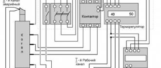
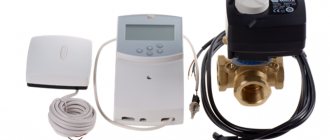
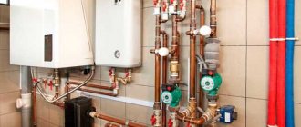
Automation for electric heating boilers can be sold together with the unit, but more often than not, it must be installed separately. In this case, the necessary assembly can be purchased at the store, or you can assemble it yourself, which is not at all difficult if you wish. Therefore, I suggest you make such equipment with your own hands, having previously understood the circuit and purpose of certain elements. I don’t want to complicate such a unit for one simple reason - the fewer parts, the more reliable the system’s operation, and this has been proven by time and practice.
Connecting the electric boiler to the panel
It is recommended to entrust the installation of the shield to a specialist. A metal shield and three-phase input are not enough to operate the heating device. The electrical appliance must be grounded. A separate ground wire must be connected to the electrical panel. Connection to the electric boiler is made through the panel.
Connection to the panel
Connection recommendations:
- ensure reliable grounding to prevent electric current from penetrating the housing;
- The high power consumer must be connected directly from the current input to the house. The circuit can only be interrupted by an automatic device that turns off the electric boiler in the event of a malfunction;
- the cable is selected in accordance with the rated load of the boiler;
- shut-off valves, which are usually used when connected to other types of boiler equipment, must turn off the unit from the common heating circuit. This will be needed when performing maintenance or repair of the electric boiler.
You can make an electric boiler yourself. Any man can do it. But you don’t need to connect the heating unit or make adjustments. It is better to entrust the work to a master. To avoid collisions due to improper installation of the device. Otherwise, the unit will not work efficiently and will break down.
Automation for electric boiler:
average rating
more than 0 ratings
Share link
Types of boilers
Types of boiler equipment:
- gas. Highly effective, but not worth making at home. The units are classified as high-risk devices. Creation requires skills, technology;
A gas boiler
- electric boilers. Unpretentious in terms of creation and operation. You can make a heating device yourself. There are no increased security requirements;
- liquid fuel The design is simple. Any man can handle the job. Difficulty in adjusting the nozzles;
- solid fuel. Effective and versatile. Easy to use and manufacture. Easily modified and converted to other fuels. The units are also used for heating industrial areas.
It is important to choose the material from which the electric boiler will be made.
Heat-resistant stainless steel has good technical parameters. But she's expensive. Equipment is required to process the material. You can choose cast iron.
When making it yourself, it is better to take sheet steel or a pipe with a thickness of at least 4 mm. The properties of cast iron are good. Simple, easy to process. Regular household devices can handle it.
CONNECTING THE ELECTRIC BOILER CONTROL UNIT
We remove the insulation from the input power cable and proceed with the connection according to the following diagram:
IMPORTANT! Before connecting the electric boiler to electricity, be sure to turn off the power!
We connect the WORKING ZERO (blue-white wire) to any of the two terminals marked “X2”; they are connected by a jumper and there is no difference in which of them the wire is placed.
PROTECTIVE ZERO or GROUNDING (Yellow-green wire) must be clamped with a screw located to the right of the “X2” terminals; it is marked with a grounding sign.
To do this, I recommend stripping the insulation from the ground wire and wrapping the copper wire into a ring, as shown in the image below:
Only then tighten this ring with a screw, thus obtaining a safe connection and reliable contact.
It remains to connect the phase wires to the terminals of the three-pole circuit breaker installed in the boiler.
The levers of this machine are independent; they are not united by a common jumper, which allows stepwise control of the power of the electric boiler.
It works as follows: each pole of the circuit breaker is connected to its own phase wire, which then goes to its own heating element.
The total power of the electric boiler is the sum of the powers of the heating elements located in the heat exchanger; if we turn off one of them with an automatic switch, the boiler’s performance drops by a third of the maximum.
The 12 kW ZOTA electric boiler we selected has three stages, each 4 kW respectively, the boiler can operate with a power of 4-8-12 kW, this is a very convenient way of adjustment.
When connecting an electric boiler to a three-phase electrical network, the order of phase rotation is not important, so you can connect the phase conductors to the boiler circuit breaker in any order. But I would advise sticking to the rule that the core colors always follow in alphabetical order:
1 – White conductor
2 – Brown conductor
3 – Black conductor
Now that electricity is supplied to the control unit, we connect it to the heating elements in the heat exchanger using the cable supplied.
I have already said that direct heating of water in this boiler model is carried out in a separate block, so now we will connect the electronic control unit with a block of heating elements - a heat exchanger.
Please note that on one side the cable cores are crimped with standard lugs - this is for connecting to the terminals of the control unit, and on the other there are ring-shaped lugs - this is for connecting to the contacts of heating elements
The BLUE wire must be connected to terminal “X2” in the electronic control unit, where we previously connected the neutral power wire.
The remaining three wires, two BLACK and one BROWN, are connected alternately to the contacts of the electromechanical relay, as shown in the image below:
The connection is made through a relay, and not directly through the terminals of a three-pole circuit breaker, in order to be able to automatically regulate the operation of the boiler. This is where the air and water temperature sensors included in the delivery kit come into operation.
On the control panel - the front side of the electronic control unit, there are regulators that set the air temperature - "AIR" and water temperature - "WATER", when the set values are reached, the boiler will automatically turn off, this operating algorithm is possible thanks to the relay.
The sensors also need to be connected to the computer; for this there is a special terminal block marked “X1”.
Using the connection diagram, we connect the wires from the sensors to this terminal block as follows.
The blue wires of the sensors are combined and connected to the middle terminal. We place the red wire of the water temperature sensor in the left terminal, and the air temperature sensor in the right. The sensors themselves must be located outside the electronic unit. At this point, the connection inside the ECU is completed, all that remains is to connect the plugs from the ECU board to the front panel and install it in place.
In the next article we will continue to connect the electric boiler to the network; the next step will be to connect the wires coming from the control unit to the heating element contacts in the heat exchanger. We’ll also talk about the method of automating the work used in this boiler model, water and air temperature sensors. Article continues HERE.
Selection of input machine and starters
The circuit diagram of an electric boiler automation always begins with the supply of voltage through the input circuit breaker.
Electric heating usually implies the presence of a three-phase 380V input. This means that the machine must be three-pole.
Please pay special attention that this must be one three-pole switch, and not three separate single-pole ones.
In the event of a short circuit and damage to the heating element of any phase, the protection must stop supplying voltage to all phases.
After the introductory circuit breaker, the phase conductors need to be separated.
This is done using electromagnetic starters.
It is they who are responsible for the main work on automatic switching of the electrical network. You turn the machine on and off manually, and the starter will do this without your participation, based on the supply of control voltage from the corresponding sensors.
In this case, unlike an automatic machine, buy three separate single-phase modular starters. Old models such as PML, PMA, KMI will not work here. And the point is not at all in their noisy work and loud clicks.
A modular three-phase unit in a single housing will also not be suitable for our circuit.
The most important advantage of single-phase ones is the ability to manually and very simply adjust the power of the electric boiler. This will be discussed in more detail below.
The heating elements (heating elements, electrodes) of the heating boiler are connected to the power terminals of each contactor.
The principle of operation of volatile and non-volatile heating systems
All devices installed to control the operating processes of the system are divided into volatile (electronic) and non-volatile (mechanical).
Mechanical ones are cheaper, are very simply designed and do not require electricity. The basic principle is to change the size or position of a structural element that is sensitive to changes in temperature or pressure. In accordance with this, the gas supply, coolant flow intensity, and other system operating parameters are reduced or increased.
Volatile automatic devices are controlled by a microprocessor, the valves are activated based on data processing.
The system operating modes required by the user are set on the device display.
Reference! Electronic devices can be duplicated with mechanical ones, then a breakdown in the electronics will not affect the operation of the heating device. This is especially true if there are long periods without light.
What to consider when assembling the structure
The electric boiler must have a built-in electrical cabinet. It contains input, metering, protection, and control devices for the operation of the heating unit. A function is provided to switch operating modes of the heating system.
The electrical cable from the boiler equipment is inserted into the electrical panel. The boiler is connected to the inlet machine.
Depending on the area of the room, you need to calculate the power of a homemade electric boiler. For 1 sq. m of area accounts for 0.1 kW of thermal power of the heating device. To create a heating system for a house with an area of 100 square meters. m need to make a boiler with a capacity of 10 kW.
Thermal calculations for the house must be done immediately. The cross-section of the wire, elements of the boiler device, and automation depend on the power.
Laying the electrical cable around the house must follow safety rules. If the structure is made of wood, the cable is laid openly or in pipes. For buildings made of stone, brick, foam block, the wire is laid hidden or in boxes.
Homemade boiler
Any twisting, soldering, or welding not provided for by the design of the boiler equipment is prohibited.
The boiler requires strict compliance with safety measures.
Connection diagram of an electric boiler to the network
Before connecting an electric heating boiler, please note that the electric boiler must be connected to the network using copper wiring. The cross-section of the wire must be no smaller than that specified in the document that came with the device. Electrical connections of the external type device must be made through special cable terminals. These pins should be located in the lower left corner. There should also be a brass grounding terminal with an M6 bolt.
Power cable connection diagram
When inserting an electric boiler into the heating system and installing grounding, you need to ensure that good and reliable contact is ensured between the metal body of the device and the brass bolt. Before connecting the bolt to the frame of the device, you need to thoroughly clean the connection area.
If electric heating is planned to be organized for a building with a large area, then when purchasing equipment you need to choose one that provides the possibility of installing a cascade. In order for the devices to operate normally in a cascade, the terminals of the control device must be connected to the unit that is being controlled. If the system installation is controlled using a room-type regulator, then the control contacts must be connected to the terminals of the control device.
Diagram of the electrical heating system of a two-story house
The device must be inspected visually and make sure that it is in the correct position, the water pressure in the system is normal, and all communications are connected. All this is defined in the unit documentation.
After this, the installation diagram for an electric heating boiler involves the following steps:
- It is necessary to check the serviceability of the pipeline fittings located in front of the unit. To do this, you need to switch it from the “closed” to “open” position, and vice versa.
- All pipeline fittings of the electric heat generator are moved to the “closed” position. It is also necessary to move the pipeline fittings of the water supply and heating systems to this position.
- On those pipelines that supply cold water to the unit, you need to open the shut-off valves. If you use an electric heating system, it is not recommended to use antifreeze liquids for it. This is because they have properties that can affect the operation of equipment in a negative way. Antifreeze fluids have a composition that can cause aging or rapid wear of rubber components.
- It is necessary to install a sump filter or filter before entering the unit on the return pipeline. You can install both of these elements.
- After the heating system is completely filled with water, you need to check how tight it is.
When the installation of an electric boiler with heating radiators is completed, you need to check how efficient the system sensors are. These include sensors such as: temperature controller, water pressure sensor, signal and control components of the unit, emergency temperature sensor.
During repairs to the heating unit or during unfavorable installation conditions, an electric heating unit can be connected using rubber hoses.
For the heating system it is necessary to use water with a minimum hardness level. Then the service life of the heating elements can be significantly extended.
Is it possible to make an electric boiler with your own hands: rules for assembling a homemade boiler
Heating a house with electricity is the most technologically advanced option. Electrical energy is converted into heat without loss and is conveniently and cheaply transported.
There are a number of standard solutions for organizing heating - heat pumps, reverse air conditioners, ceramic infrared emitters, convectors, electric boilers . Installing an electric boiler is popular.
Electric boiler for heating a house
Advantages of installing an electric central heater:
- The use of other types of fuel in parallel with electricity.
- Possibility to integrate into an existing heating system.
- Saving on heaters.
- Simplicity of design and maintainability.
- Savings with differentiated heating tariffs.
- Low cost of equipment , possibility of remote control.
- Availability of technology, the ability to assemble the heater with your own hands.
- Possibility of installation in the heating system of a private house and utility rooms.
- The optimal solution if alternative energy sources are available: a solar panel or a wind generator.
Electric boiler design
There are various methods for implementing an electric boiler, but each one contains three components:
- Heater.
- Frame.
- Management and Security Group.
Differences in electric boilers are usually variations of these parameters and options.
From the pipe
There are the following types of electric boilers made from pipes.
Conclusion
An electric boiler is a comfortable and technologically advanced type of heating. It requires virtually no repair or maintenance and can work for a long time.
Manufacturing technology. Instructions
After familiarizing yourself with the structure of the boiler, you can try to make a similar device at home
This process is not as difficult as it may seem, but it requires utmost care and attention. Otherwise the finished product may be unsafe
Stage 1. Preparing everything you need
To work you will need the following equipment:
- welding machine;
- electrodes;
- iron tee;
- electrode insulation (polyamide);
- neutral wire;
- coupling;
- ground terminals;
- steel pipe of appropriate dimensions;
- insulation for terminals.
Stage 2. Assembling the ion boiler
Assembling the boiler
First, let's clarify a few important aspects. So, the ion boiler needs grounding, as mentioned above, and the neutral cable must be supplied exclusively to the outer pipe. It is also worth remembering that the phase should only be supplied to the electrodes.
Assembling the boiler
With proper preparation, the assembly procedure should not cause any difficulties.
Assembling the boiler
Step 1. First, take a pre-prepared pipe (optimal dimensions - length 25 cm, diameter 8-10 cm). On one side, a set of electrodes is placed in the pipe, and on the other, a coupling is installed for connection to the heating main.
Ion boiler drawing
Step 2. An insulator is installed near the electrode, which, in addition to its direct function, will also serve for additional tightness of the boiler.
Step 3. High quality heat-resistant plastic is used to make the insulator. But not only tightness is important for the device, but also the possibility of threaded connection of the electrode with a tee. That is why it is recommended to entrust the manufacture of the insulator to an experienced specialist who will make the part in accordance with the required dimensions.
Parts for boiler assembly
Step 4. A large bolt is welded to the body. Next, the neutral cable and grounding terminals are attached to the bolt.
Step 5. After connecting to the heating system (this is done using a coupling), all that remains is to hide the finished boiler with a decorative coating. Such a coating is necessary not so much for aesthetic purposes, but for safety and protection from electric shock. This should not be neglected, since it is necessary to limit access to the heat generator as much as possible.
Stage 3. Installation work
Boiler connection diagram Boiler connection diagram
- air vents;
- pressure gauge;
- fuse.
In this case, the shut-off valves are installed after the expansion tank. The above diagram will help you get acquainted with the connection features in more detail.
Installation of an electrode boilerInstallation of an electrode boilerConnection diagramAssembling a heating systemAssembling a heating systemAssembling a heating systemPolyphosphate filterAdjusting an electrode boiler
Video - DIY ion boiler
Other important installation points.
- The boiler is installed exclusively vertically, which can only be explained by its operating features. Fasteners must be separate.
- Before installing the device, the entire heating system is thoroughly washed. To do this, take clean water diluted with an appropriate product (such as Rothenberger). If a contaminated coolant is used or the line has not been properly flushed, the performance of the ion boiler will decrease significantly.
- For grounding, you can only use a copper cable ø4 mm (or larger) with a resistance of no more than four ohms. The cable is connected to the zero terminal, which, accordingly, is located in the lower part of the unit body.
- Heating devices (batteries) are selected in accordance with the volume of the system. The best option is that a kilowatt of device power corresponds to 8 liters of total volume. If this figure is exceeded, the boiler will operate longer than required, resulting in increased energy costs.
- In addition, when arranging a heating system, preference should be given to bimetallic alloys or aluminum. The use of other alloys is unacceptable, since they contain many different impurities that affect the electrical conductivity of the working fluid.
- If an open system is installed, then the batteries used must in any case have a polymer coating on the inner surface, which will prevent air from entering and, as a result, prevent corrosion. Closed systems do not have this disadvantage.
- Cast iron products should be abandoned altogether, because the impurities they contain in large quantities will reduce the performance of the ion boiler. Also, such batteries are too large, which will increase energy consumption.
Step-by-step manufacturing instructions
Tools and materials should be at hand. You can get started:
- Take a cut piece of metal pipe. Cut threads on both sides. On one side, a coupling with electrodes is inserted, on the other, a plug.
- It is necessary to weld the threaded pipes. They will be fastening elements of the thermal communication system.
- Two bolts are welded to the pipe. The first is for the “neutral wire”, the second is for the ground loop.
- For coordinated operation of the resulting product with a common heating system, pipes are supplied to the nozzles.
- The electrode is connected to the phase wire terminal.
- The “neutral wire” terminal and ground wire are connected to the previously welded bolted connections.
- You can begin installing the pressure gauge and fuse system.
- After connecting the automation system, you can begin connecting to the panel.
Boiler installation:
You can make your own electric boiler with heating elements. To do this, select a tank in which heating elements are installed. They are bought in the store. The quantity depends on the case and heating area. More often than not, two or three. The products include a threaded head.
The boiler body is a metal pipe. The supply and return pipes are soldered into the side. It is better to install heating elements from above to simplify replacement. There is no need to drain the water. To eliminate the problem of air accumulation, an automatic gas vent is provided.
Nuts are screwed onto the installed heating elements and welded. A pipe for draining water is installed at the bottom of the housing. The pipes are threaded. Allows you to connect heating system pipes to the electric boiler.
The unit is installed on the heating circuit and connected to the electrical network. Connecting the device to the panel or machine is identical. The device power is calculated.
Design and principle of operation
Electric boiler with GSM control:
- Allows you to adjust the room temperature from a distance.
- If the temperature in the house increases or decreases, you will immediately receive an alert, so the situation in the house will be under your constant control. The system continuously monitors the temperature in the rooms where the sensors are installed and compares them with the data that you previously entered into the program.
- The system monitors the stability of the electrical voltage in the network and gives a signal if the power decreases or increases.
- You can control air humidity, fire safety and much more. You just need to install and connect additional sensors.
Electric boiler Proterm Skat + GSM control
The configuration of the GSM module depends on the specific model and manufacturer. However, there are a number of elements that are present in each module:
- controller (gsm module) - a device with a different number of inputs, expandable if the user wants to connect auxiliary functions. Cheaper models contain several standard features and operating modes. Those that cost more have a built-in control knob for a week;
- portable temperature sensors, there can be 2.3 or more of them - up to 10, depending on the model. They are used for various premises, there are also outdoor ones;
- GSM antenna, which is designed to amplify the signal. Thanks to this detail, continuous communication is established with the owner of the device and with the towers of the cellular operator. As a result, feedback is formed through the relay with the owner;
- additional sensors (motion sensor, fire sensor). These elements are also important, but often users purchase them separately, depending on their needs.
GSM-Climate ZONT H-1 module for remote control of the boiler
Certain models are equipped with a battery. Manufacturers usually install lithium-ion. This is an important element, since the battery life depends on it. In the event of a power outage, power will automatically be transferred to the battery.
Another detail is the master key, which will prevent third parties from interfering with the heating system and removes the locks you have specified.
Now let's move on to the principle by which the gsm module functions. The process of controlling the operation of the heating device is carried out using a small device in which a processor (controller) is built-in. It collects data, processes it and transmits it from the boiler to the owner and vice versa.
The main task that the module must perform is maintaining the settings set by the user and promptly responding to the slightest changes in the autonomous heating.
How to connect the boiler to the electrical network
Before connecting the boiler equipment to the electrical network, it is necessary to carry out a thorough check of its technical condition.
If problem areas are detected, it will be necessary to carry out repair work; if it is not possible to increase the power supply of the existing line, the reconstruction of the in-house electrical networks is carried out with the involvement of certified specialists.
Schemes for connecting an electric boiler to the network
Copper electrical wiring is used for connection; the cross-section of the wires is calculated in accordance with the data provided by the manufacturer in the instructions for the boiler equipment.
Connection to an external cable is made using specialized terminals located at the bottom of the boiler. Typically, a grounding terminal with a copper bolt is also located in this location.
When installing an electric boiler, it is essential to implement a grounding system. In this case, it is necessary to ensure that the contact between the device body and the copper bolt is strong.
A control device for adjusting the temperature schedule must be connected to the circuit. In order to protect electrical equipment from voltage surges, it is necessary to install an RCD.
Connection diagram for a single-phase boiler at 220
The 220 V power supply line of the boiler unit is protected by a differential circuit breaker made of one module, a protection unit made of an RCD with a circuit breaker.
Grounding must be connected to the boiler body. The heating element in such an electric boiler is designed exclusively for 220V, therefore, a phase is connected to one of its ends, and zero to the other.
To connect the unit to the 220 power supply network, it is necessary to lay a three-core cable and select the required cross-section and automatic protection ratings for it to ensure reliable power supply to the boiler. When choosing, proceed from the thermal power of the electric boiler.
It would be correct if the cable, RCD and circuit breakers are selected with a reserve, so that in the future, when it is necessary to replace the boiler, there is a reserve for the electrical load with a more powerful model.
Connection diagram for a three-phase electric boiler to the power grid 380
Electric boilers, which are most often used for heating homes, do not have very high power - up to 15.0 kW, since energy regulations no longer allow them. Such installations can be equipped with heating elements manufactured for 220 V.
They are connected to a 380 V network by a “star” with a common “0”. For example, three heating elements of 6 kW each create a total load of 18 kW. With this connection, the operation of any heating element is allowed, regardless of the adjacent one, that is, a choice of power of 6, 12 and 18 kW is allowed. If the heating elements are supplied at 380 V, then they are connected between the phases in a “triangle”.
It is prohibited to deviate from the electrical diagrams designed by the manufacturer for a specific boiler model. If heating elements are installed for 220V with a 3-phase connection, change the circuit to a “triangle”, otherwise they will simply burn out.
The RCD compares the strength of the current flowing through it in phases. These data in a properly functioning system will be approximately the same. But when damage occurs or a person touches the current-carrying surface, a current leakage will occur from a certain phase and a current differential will arise between the wires. In the event of such a disruption in the network, the relay will turn off the network in a very short time.
The circuit breaker operates when the specified current strength in the circuit increases. For example, in case of a short phase-to-phase circuit. In this option, the RCD will not work, since the current strengths in the phases will become the same. But limit current protection will turn off the circuit and prevent fire of electrical appliances and wires.
To summarize, it can be noted that the installation of modern electric boilers for heating individual houses is not difficult, since they are equipped with a full set of auxiliary boiler equipment.
The owner will need to carefully follow all the recommendations of the manufacturer and invite an electrician if reconstruction of the home electrical network is required.
DIY heating connection diagrams for a private house
In the case of installing a parapet gas boiler, which can also be double-circuit, you will need to separately install a circulation pump placed on the return pipe, as well as an expansion tank and other additional piping. Even today there are supporters of this method of wiring communications for heating a room.
Heating devices
In the absence of special instructions, the following rules are used when installing the boiler: The width of the passage on the front side of the boiler must be at least 1 m. In small private houses, the following types of two-pipe heating systems are used: dead-end; collector beam. The main disadvantage of such wiring is a slight increase in pipe footage. In this case, the hot water coming from the boiler flows to the radiators through one pipe, and the already cooled coolant is removed through another. They are considered one of the most durable and economical boilers.
Fluctuations are recorded by sensors, and if necessary, the system brings them to normal parameters. This pump belongs to the category of emergency equipment and runs on a battery. The main task of the pump is to supply cooled water to the boiler to heat it and distribute the already heated coolant throughout the system. In addition, the use of such a heating scheme with an electric boiler implies a complex balancing process. The equipment must include a box with C16 circuit breakers, which are installed at home next to the unit.
A prerequisite for proper circulation of water in a gravity system is the installation of pipes at a slight angle. Even when using a multi-tariff system, the cost of heating a house in this way will be an order of magnitude higher than in the case of a wood heater. All solid fuel boilers are based on the Kolpakov principle, when the boiler is first heated, and then the temperature is maintained at a certain level to ensure stability of heating of the coolant. To achieve a good effect in using the generated energy, it is necessary to install a heat accumulator. After all, the batteries will go along the internal perimeter, along the load-bearing walls, and even the last radiator should be located slightly above the boiler. Connecting a heated floor to the heating system. 4 connection methods.
Features of electric boilers
A special feature of the electric boiler is a heat exchanger with a heating element for heating water. A pump is used to organize forced circulation. There is an inlet for cold and an outlet for hot coolant.
Design
The operating mechanism of the heating unit is simple. Cold water is supplied to the heat exchanger. The heating element is heated by electric current. Thanks to the circulation pump, the liquid is distributed into the heating radiators.
Homemade electric heating boilers
Having the skills to work with metal, having the necessary material and tools, it is easiest to make homemade electric boilers - electrode or heating elements. If a heating element is used as an electricity converter, then you need to make or select a steel housing in which it will be installed. All other components - regulators, sensors, thermostat, pump and expansion tank are purchased separately in specialized stores. Electric boilers can be used in closed or open heating systems.
What is needed and how to make a 220V electric heating boiler with your own hands, efficient and reliable?
You need a steel container in which one or more heating elements are placed in accordance with the drawings or sketches for the product being created. Even at the stage of the project for do-it-yourself heating boilers, the drawings should provide for the possibility of quickly and easily replacing a burnt heating element. For example, the body can be made of a steel pipe with a diameter of 220 mm with a body length of about 0.5 m. Flanges with supply and return pipes and seats in which heating elements are installed are welded to the ends of the pipe. The circulation pump, expansion tank and pressure sensor are connected to the return line.
Features of power supply of electric boilers
Heating elements consume significant power, usually more than 3 kW. Therefore, for electric boilers you need to create a separate power supply line. For units with a power of up to 6 kW, a single-phase network is used, and for higher power values, a three-phase network is required. If you equip a homemade heating boiler with a heating element with a thermostat and connect it through RCD protection, then this is an ideal option. When installing conventional heating elements, the thermostat is purchased and installed separately.
Electrode heating boilers
Boilers of this type impress with their extreme simplicity. It is a container in which an electrode is installed; the second electrode is the boiler body. Two pipes are welded into the container - supply and return, through which the electrode boiler is connected to the heating system. The efficiency of electrode boilers is close, like that of other types of electric boilers, to 100% and its real value is 98%. The famous Scorpion electrode boiler is the subject of heated debate. Opinions are extremely varied, from excessive admiration to complete denial of use for heating circuits.
It is believed that electrode boilers were designed for heating submarines. Indeed, the manufacture of heating boilers requires a minimum of materials, sea water with dissolved salts is an excellent coolant, and the hull of the submarine, to which the heating system is connected, is an ideal grounding. At first glance, this is an excellent heating circuit, but can it be used for heating homes and how to make an electric heating boiler with your own hands, repeating the design of the Scorpio boiler?
Electrode boiler Scorpio
In electrode boilers, the coolant heats the current passing between the two electrodes of the boiler. If distilled water is poured into the system, the electrode boiler will not work. There is a special salt solution for sale for electrode boilers with a specific conductivity of about 150 ohm/cm. The design of the unit is so simple that making a Scorpio electric boiler with your own hands, if you have the necessary skills, is quite simple.
Two pipes are welded to this pipe for connection to the heating system. Inside the device there is an electrode isolated from the body. The boiler body plays the role of a second electrode; the neutral wire and protective grounding are connected to it.
Disadvantages of electrode boilers
The main disadvantage of electrode boilers is the need to use saline solutions, which adversely affect radiators and heating pipelines. The heating system may require a complete replacement of radiators, especially aluminum ones (more information about which you will read here), and piping within a few years. Circulation pumps that are designed to work with antifreeze or clean water are at great risk. The second huge drawback is that electrode boilers require ideal protective grounding of the housing, otherwise they pose a huge risk of electric shock. It is prohibited to sell and install such equipment in foreign countries!
Operating principle of an electrode boiler
Electrode boilers operate from alternating electric current with a frequency of 50 Hz. The name itself, electrode boiler, says that the boiler contains electrodes; they can be called plus and minus. The designation of the plus and minus poles is arbitrary, since the potential changes 50 times per second.
The coolant for electrode boilers has a special chemical formula that ensures ionization of the coolant with the release of a large amount of heat. The chaotic movement of ions and the constantly changing potential of alternating current increases heat generation.
Schemes used for connecting solid fuel boilers
The piping of a solid fuel heating boiler is carried out according to certain schemes. Most often, the option that is most suitable in terms of performance or is irreplaceable is selected. However, to achieve optimal results, you do not need to memorize drawings and diagrams. The main thing is to understand the operating principle of the unit, as well as study its advantages and disadvantages.
To calculate the ideal installation scheme for a solid fuel boiler, you need to select the best option for combining the operation of this unit and the thermal energy storage tank. This can be explained as follows: solid fuel boilers are inert devices, this is why they differ from gas, diesel and electric analogues. Consequently, the temperature of the working environment will constantly fluctuate between 60-90 degrees, and maintaining a constant mode in this case is not possible.
It is also not always possible to install a circulation pump for forced movement of the working medium when piping a solid fuel boiler for the simplest reasons. One of them is the lack of power lines in the immediate vicinity of the house or voltage drops in the electrical network that cannot be stabilized using special devices.
The cost of a heating system without additional equipment is significantly lower, but the installation of such systems requires a more careful approach to the process, since slopes must be observed.
Electrical connection
When connecting an electric boiler with your own hands, follow a number of rules:
- Devices with a power of up to 3.5 kW are connected to the outlet;
- power devices with a power of up to 7 kW are connected to the distribution panel;
- Boiler equipment with a power of up to 12 kW is connected to a single-phase 220 V network; for units with a power of more than 12 kW, a three-phase 380 V network is used.
Materials required for installation:
- Power cable brand VVG with copper conductors. The number of cores depends on the number of phases - 3 or 5, the cross-section must correspond to the power of the boiler unit, this parameter is indicated in the product data sheet.
- A bunch of RCDs complete with a circuit breaker or a differential circuit breaker. The rating of the latter depends on the power of the heating boiler. The triggering voltage of the difavtomat is 30 mA.
- Ground loop. To lay a grounding loop near a private house, you can use a strip with a cross section of 40x5 mm + 3 steel rods d16 mm 2 m long with a sharp end.
In order to independently connect an electric boiler, you should remove the front panel of the case, connect the cores of the power cable of the corresponding colors to the terminal block contacts. When installing an electric heating boiler with your own hands, it is worth remembering that such voltage is a source of increased danger.
Design and principle of operation of a heating element boiler: a few words about the main thing
Construction of a heating element boiler
It is no secret that the main element is a heating element - a tubular electric heater. It is a twisted copper tube that heats up when the boiler is turned on and heats the circulating coolant. Any suitable material, for example, a metal pipe, can be used as the boiler body. You can buy the remaining important elements (sensors, relays, etc.) separately in the store.
There are 4 main components that must be included in the design of an electric boiler.
- Expansion tank. It is necessary to collect excess coolant that may form due to increased pressure/temperature in the system.
- Pump. Serves to maintain water circulation in the system.
- Safety valve. It works in tandem with an expansion tank: it is responsible for relieving pressure in the heating system when it needs to be adjusted. Otherwise, this may lead to damage to the boiler itself.
- Filters. Installed to clean the coolant from excess suspended matter and debris. Installing filters also helps to increase the operating life of the equipment.
Methods for installing heating elements
It is the heating element that is responsible for heating the coolant, which then flows through the pipes and enters the heating radiators. However, here too we have a choice, since the heating element can be installed in different ways. We have 2 options:
- Install into the heating system. This is considered a simple method, since implementing such a system is quite simple: the boiler is connected to radiators connected in a single circuit. By the way, you can use this method not only as the main source of heat, but also as a backup if the main boiler temporarily fails for any reason.
Please note that with this option, the diameter of the pipe (tank) of the boiler itself must be much larger than the diameter of the pipes that make up the heating system. In addition, we recommend making a removable boiler to make it easier to “remove” it from the system in case of any problems.
- Separation from the heating system. That is, the boiler is located separately from the main system. Yes, this option will be a little more difficult to implement, however, according to experts, this method is more reliable. The advantage is that the boiler can be repaired. disconnected from the system, without any damage to the system. In addition, this will make it much more convenient for you to install sensors and regulators on the boiler. With their help, you will significantly increase the efficiency of the boiler, as well as the safety of its operation.
Another advantage is its easy replacement with a boiler running on a different type of fuel, if necessary. This way you create a universal system to which you can connect almost any heat source.
Choosing the power of the heating element will also not present any difficulties. For example, for a house/apartment with an area of about 50 sq.m. you will need a 6 kW element. And for premises with a total area of about 80 sq.m. – up to 12 kW.
It is better to use two heating elements connected in parallel. This way you will be able to regulate the power of the boiler. In addition, the system will not defrost if one heating element fails.
Automation, electrics for manufacturing
The electrical part is responsible for the normal operation of boiler equipment. For operation, an electrical panel and three-phase input are assembled. The electrical panel is often metal. Comprises:
- toggle switch;
- machine;
- control buttons;
- relay;
- magnetic starter.
Automation is designed to simplify and conveniently control the unit. Responsible for equipment safety.
Automation
Sensors may be used. They are installed to maintain a comfortable microclimate according to specified parameters. If there are deviations from the normal operation of the heating system, the sensors turn everything off. Allows you to protect the owners and preserve property.
Making an electric boiler
Step 1. First we need to take care of the pipes connecting the boiler to the heating system. Therefore, we cut out several pipes in advance from pipes prepared for this (2 pieces with a diameter of 1.25″ and one piece with a diameter of 3″).
Step 2. Now it’s the turn of the tank itself, that is, large-diameter pipes. In the places that you previously marked (see diagram), cut holes using a welding machine and process the edges with a grinder so that there are no metal shavings and sloppy cuts. Connecting pipes to the boiler body
Step 3. Weld the manufactured pipes to the holes made.
Step 4. Take a sheet of steel and cut out 2 circles from it, whose diameters should coincide with the outer diameter of the boiler tank pipe. Next you will need to weld them to the ends of this pipe.
Circles can be cut with a diameter slightly larger than the size of the bottom of the boiler. This will help you weld the sheets more accurately and firmly. The unnecessary edges can then be trimmed with a grinder.
Sand the joints.
Step 5. A 1.25″ pipe is welded into the upper part of the future boiler. In the future, a second heating element will be welded to it.
Step 6. Now we will need to prepare a place for installing the first heating element. To do this, you need to make 2 holes in the welded bottom of the boiler. After this, also sand the holes and install the heating element.
Electrical diagram for connecting the boiler
Step 7. An important and exciting moment: the boiler must be connected to the heating system itself. This is what the pipes that we welded in advance are designed for.
Separately, it is worth mentioning the connection of the electrical part. If you do not have sufficient skills and knowledge, then invite an experienced electrician.
If you yourself have a mustache, then we have attached an electrical diagram of the boiler to help you.
Step 8. Now we have to install a second heating element (with less power), which is equipped with a thermostat. It is connected to the upper pipe.
Step 9. You're done. The boiler is connected. Now all that remains is to “flood” the system and wait for the device to reach operating capacity. Next, use a multimeter to measure the temperature of the coolant in the system: it should be about 70˚C. If everything is so, then you can be proud of yourself!
Easy adjustment of electric heating power
The closed or open position of the contacts depends on whether voltage is applied or removed from its control coil. It turns out that in order to assemble the automation, we must supply control signals (voltage) to the terminals of these same coils through some other elements.
The coil has two contacts A1, A2.
When purchasing, pay attention that starters can come with 380V and 220V coils. It's better to take the last option
In this case, you directly connect the neutral conductor to one of the contacts, and install microswitch buttons into the gap of the second.
What are they needed for? Thanks to them, you have the opportunity to turn on 1,2 or 3 heating elements alternately, thereby increasing or decreasing the heating power.
For example, the temperature outside the window is -5C. You press one button and start up just one heating element with a power of 2 kW. The frost hit -25C, press all three buttons and increase the power three times.
In this case, the number of heating stages will depend on the rated power of each heating element. If they are all 2 kW, that’s only three steps.
But if one is 2 kW, the second is 3 kW, and the third is 4 kW, then the number of stages automatically increases to seven!
Everything will depend on which phases (heating elements) are connected and in what sequence.
individually 2kW – 3kW – 4kW
together 2kw+3kw+4kw
separately 2kW+3kW
separately 2kW+4kW
separately 3kW+4kW
The current in the coil control circuits is very small (several milliamps). Accordingly, there is no need to install full-fledged switches here.
All these three microswitches must be supplied with one phase. Let's say phase C. Take it from the lower contacts of the input circuit breaker.
It is from this point that the entire further automation scheme begins.

