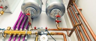
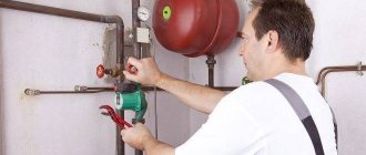
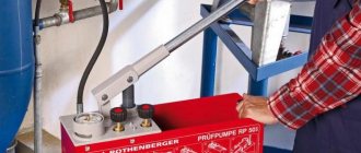
During the operation of utility and engineering infrastructure, maintenance and preventative measures for the operation of lines play an important role. With their help, damage is detected and sudden changes in voltage are recorded. One of the most effective methods is crimping. Manual pressure testers are necessary for testing and preventive inspection of heating systems.
When checking the heating system, a manual crimper will come to the rescue
Pressure testing pump: main purpose
During operation of the heating system, some changes in parameters appear, for example, radiators, pipes, boiler or pipes at the joints. What is pressure testing and how does it identify such problems? This question is very interesting for people who have connected heating systems.
When a series of works is carried out to install a new heating system or repair an old system, there is a small likelihood of cracks at the joints of the system. A unit designed for pressure testing identifies such problems before starting the system. The operation of such a device is to create high pressure in the required area or in the entire heating system. Pressure monitoring or visual inspection may reveal problematic connections.
Crimping is necessary in 4 cases:
- After completion of repair or installation work;
- Before the heating season begins;
- After system maintenance;
- After replacing some system components.
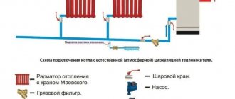
To carry out this type of work, pumps are used to create pressure testing in the heating system. Such pumps are pneumatic and hydraulic. Experts recommend drawing up a schedule for carrying out pressure testing of the heating system of a house or apartment. But before that, you need to understand the technology of the crimping process and choose a device for it.
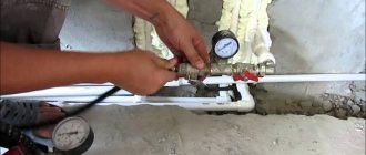
The device of the crimping machine and its main functions
The crimping machine is based on a pump unit responsible for the working force.
Among the remaining elements, the following must be highlighted:
- container with liquid;
- hoses;
- a set of controls;
- pressure gauges.
Thanks to the latest device, it is possible to assess the technical condition of pipelines. The pump itself is made of steel and durable composites. When choosing, the weight of the device is taken into account, which affects the conditions of transportation and use. Typically, the weight of a hydraulic pressure tester varies from 5 to 7 kg.
More information about the hydraulic crimping machine:
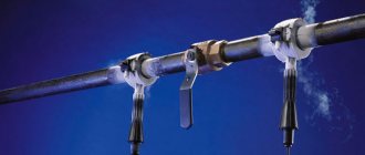
Pressure testing is carried out to detect leaks and measure stress in pipes. Although modern pumps have a much wider range of functionality. They are used as a device that detects damage in individual sections of lines. Inspection work is required after repairs and installation of new pipelines. It is impossible to put a finished object into operation without preliminary crimping. The pump is used to check the reliability of pipe connections before the heating season.
To check a certain section of the lines, it is filled with water, and oil or other special liquid is poured into the pump reservoir.
When the circuit is filled to the maximum level, the machine will begin to record pressure through the main relay. Pressure testing lasts two to three hours, during this period it is necessary to ensure stable operation of the pump. At the end of the procedure, the pressure is measured again and compared with the primary values. This is interesting: characteristics of the circulation pump.
Different devices differ in work time and power. Each network requires a machine with a suitable internal pressure range. If the readings at the beginning and end of the procedure are different, then there is a leak in the pipeline that needs to be fixed.
More details about hydraulic pump and hydraulic coupler:
What is a pressure test pump?
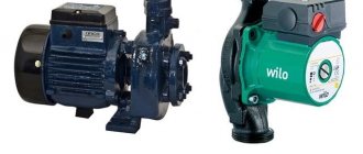
We already know what crimping is and how to carry it out. Now you need to understand the types of devices used. In order to carry out this work, special installations are used; they differ in configuration, design and technical parameters.
Hand pumps operate on the basis of a piston system to generate pressure.
Electric pumps for pressure testing systems are power pumps and build up pressure with the liquid in the system. All such pumps are suction pumps. To perform large volumes of crimping work, it is recommended to use only electric pumps, and for small volumes, mechanical pumps can also be used.
These 2 types of pumps differ in design in the following ways:
- Membrane structures;
- Piston structures;
- And plate-rotor ones.
Almost always, to create pressure testing for heat supply in an apartment building, only piston ones are used, since they have an acceptable cost and are reliable. If you plan to inject liquid into the system, it is better to install a different type of pump. In this situation, the best choice would be a diaphragm type of pump. With the help of such pumps you can very quickly and do pressure testing of the heating system yourself.
Pocket crimper according to GVK recipe
Ansem wrote: Since I plan to use the structure many times, I assembled the structure shown in the photo. From left to right there are 1 Fitting 10mm by 1/2″
Strange, this garden sprayer usually has a plastic thread M12x1mm. To cut threads in a 1/2″ adapter, it is best to take a full-bodied nut from a Mayevsky faucet made of white brass (I haven’t seen any others) with a plastic corrugated white cone-shaped handle (not a key or square). With the same sprayer as the starter top and DED, I developed a pressure of 22 atm, it’s scary to pump further by the handle. In the scheme without an additional check valve, with its own. Why does the sprayer pump such pressure? Because its piston pumps not air, like modern ones with a pump where you can’t get more than 3 bar, but water! Therefore, only sprayers for bottles or containers that are large enough and have a large handle and piston are suitable. Sprayers with a pump and pre-pumping are not suitable - they pump air into the container, which displaces water into the tube. These same ones suck WATER into the PISTON through a tube, and then it is sprayed out, and water is not compressible, unlike air. Toy, small disposable ones are not suitable, their handle is specially weakened and the piston joint is made in such a way that it breaks after a certain number of strokes. So that you buy new bottles with a Mr. Muscle type sprayer. ======================================= Experimented with a high-pressure mini washer and an electric pressure switch for 12 bar. The relay was installed at the end of the standard hose through a homemade 1/2″ adapter from the handle of the mini-wash hose. When turned on, the pressure reached 40 bar, the relay seal and the unipak on the threads broke, the pressure dropped to 30 bar. 2 flexible hoses held up, but with the old one a lot of black, oily small debris came out - the rubber was probably falling out. When the pressure was gradually released, the relay turned on the mini-wash at 12 bar as expected. Why didn't it turn off in time? The long elastic high-pressure hose and the inertia of the water mass played a role, plus the inertia of the engine flywheel and pistons. Therefore, the delay in the relay reaction time was enough to increase the pressure to 40 bar. It is necessary to install a pressure relief valve reconfigured to 15 atm, for example 12 atm Adjustable safety valve DN15 VT-1831 Valtec. And in professional systems like Ridzhik, the pressure switch and emergency valve are located not after the hose, but on the pump itself, without elastic adapters. In general, a mini-wash can tear the battery and pipes like a hot water bottle and give pressure up to 100 atm.
As an option, a CO2 cylinder gives a pressure of 60 bar. We put it on a fire extinguisher with a valve! a throttle washer with a hole of less than 1mm and smoothly apply pressure through the brake hose from the Gazelle, which with its thread fits perfectly into the M 16x1.5 cylinder, and at the other end of the M 10x1mm we make an adapter for 1/2″. With a valve and a throttle, it’s quite possible to get 15 bar.
The working pressure of modern thermal valves is 10 atm, so the test pressure test is 15 atm for 30 minutes minimum. If there is a bare bimetallic battery, then up to 25 atm. And depending on your luck.
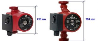
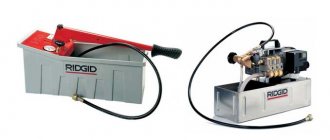
Electric pump for heating testing
The electrical device for crimping systems is equipped with a motor and operates from a network with a voltage of 220 volts. This pump is used to test plumbing, heating and oil systems. It can only be used for professional work under heavy loads.
An electric type pump has the following main advantages:
- Ease of use and maintenance. To start crimping, you must press the button on the power supply.
- Productivity level is high. Using an electric drive, it delivers maximum pressure in minimum time.
- The service life of the unit is very long, as it is made of very high quality and in a reliable housing.
- Has a bypass valve. The presence of such a valve makes it possible to regulate the pressure.
- This pump is also equipped with special overheating protection. If the unit overheats, this system automatically lowers the pressure level, which means that the pump cools down.
- This type of pump is mobile. It can even be transported in the trunk of a car.
There are also disadvantages to this device. Such a pump costs a lot of money, runs only on mains power and is heavy.
Which jack to choose
For the manufacture of a press from a jack, single-rod bottle-type devices are optimally suited, which are distinguished by a simple design and high reliability. Presses made on the basis of such a jack have higher power when compared with equipment whose main working body is lever, crank, screw or eccentric mechanisms.
Press with hydraulic jack
Various models of hydraulic jacks are capable of creating a force, the value of which varies in the range from two to one hundred tons, which allows them to be used as a very effective power mechanism.
Hydraulic jacks, along with high power, are distinguished by fairly compact dimensions, which allows them to be used for the manufacture of presses that will not take up much space in a workshop or garage, but at the same time will be highly efficient.
Do-it-yourself pressure testing pump
In order to perform crimping, it is not necessary to purchase a special device. You can make a device such as a pressure testing pump yourself. To do this, you will need to have some spare parts and elements.
You can use an old jack and cylindrical containers.
Devices of this type have an average capacity of 50 liters and can operate at a pressure of 10 bar. The arrangement of pump elements with system elements is carried out using a threaded connection. Holes must be made in the cylinder. Among the holes there must be one for supplying liquid, the second for a pressure gauge, you will have to buy it. This is a manual version of the pump for crimping pipes.
A homemade pressure testing pump is great for pipelines before starting hydraulic tests. The crimping machine can be not only manual, but also mechanical.
What is needed to make a press
The drawings of such a device allow you to make a press from a jack with your own hands. They are easy to find on the Internet in the public domain.
Drawing of a homemade press from a hydraulic jack
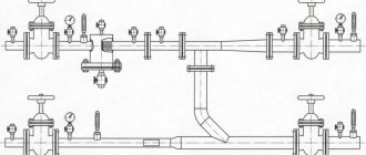
To make a hydraulic press from a jack, you should also prepare:
- the hydraulic jack itself is of a single-rod bottle type (for a press that will be used at home, a jack that develops a force of up to 10 tons is also suitable);
- inverter with a set of electrodes;
- hacksaw for metal;
- grinder with a set of discs designed for cutting metal;
- a section of channel size 8 and above, 4 m long;
- square or rectangular profile pipe with thick walls;
- equal-flange metal corner No. 50;
- steel strip having a thickness of more than 10 mm;
- a piece of pipe 10–15 mm long, the diameter of which should match the size of the jacking rod;
- metal plate measuring 25x10 cm and thickness 9–10 mm;
- two springs that are needed to return the stop to its original position (springs from car seats, doors, etc. are suitable).
Channel blanks
Let's look at the process of creating a press step by step
To make devices, you will need to purchase:
- Channel No. 8 3 m. (width 8 cm). In order not to suffer, it is better to immediately cut it into pieces of 50 cm.
- A rectangular pipe 4 by 6 cm, also 3 m. Again, it is better to cut it on the spot, 2 pieces per meter, and 2 pieces 50 cm each. The cost of the pipe and channel, including cutting, will cost about 33 USD.
- Bottle type jack for 12 tons. The cost will be approximately 31 USD.
- Door spring 30 cm - 2 pieces (then they will have to be cut to 20 cm) 2.6 USD.
- Bolts M12 x 80 and nuts for them 10 pcs.
- Bolts M10 x 80 and nuts for them 4 pcs.
- M12 bolts for 150 2 pcs.
- Bolts 8 to 30 4 pcs.
- Small two-legged puller, 3.7 USD.
- M16 studs per 1000 – 2 pcs.
- M8 stud for 1000 – 1 pc.
- High nuts M16 – 4 pcs.
- The total cost of fasteners will be about 12.2 USD.
In addition to the above materials, to make a homemade press from a jack, we will use the following:
- Fungus from the axle hub with shifted splines (unsuitable for use)
- Plate 25 by 25 by 0.8 cm
- Stripe 0.4 by 4 cm – 4 by 60 mm
- Corner 50 by 50 – 2 by 30 cm
- Corner 25 by 25 – 2 by 5 cm
- M8 nuts – 4 pcs.
In the image you can see what you should get. There is no jack fastening, which means that it can be easily removed and used for other purposes. The diameter is 23 cm in height:
Drilling channels should be done in pairs, to begin with, 0.4 cm in diameter, with the holes aligned along the way, for example, using a cotter pin, and then 1.25 cm:
The fungus is fastened using 8 x 30 mm bolts. Thread cutting can be done in a channel, or maybe on a nut:
Now trimming all the excess:
Now the spring. The original length of the spring (not including the 30 cm bent coils) should be shortened to 20 cm
Finally, when all the holes are drilled, the “legs” should be welded. Hooks on the puller: legs that are welded onto high M16 nuts
Puller appearance:
The top of the puller, which consists of two strips 40 by 4 by 60 and a high M16 nut, is prepared for welding:
Top and bottom of the puller after welding:
Photo of the differential clamped in the puller and the process of pressing the bearing:
The position of the lower support, which includes two channels, can be set at intervals of 10 cm (3 positions)
Well, that’s all, the homemade press from a jack can be considered ready.
Additional settings
When using a homemade hydraulic press, users often have a question about how to make the jack rod move a shorter distance. This will allow you to spend less time processing parts using a homemade press. There are several ways to solve this problem.
- A rectangular or square profile pipe is mounted on the lower fixed stop of the press (either a removable version or fixation using a welded joint is possible).
- A height-adjustable lower stop is installed on the press, which is fixed to the side posts of the device with bolts. To install such a stop at different levels, holes are made in the side posts of the press at the required height.
- The distance between the press stops can also be reduced by using replaceable pads or anvils installed on the surface of the lower stop of the equipment.
Source: met-all.org
FakeHeader
Comments 71
Calculate the design according to strength of material - 10t is the limit... Not enough, although it’s unlikely that more is needed in the garage.
My friend, what do you use to drown the batteries in the garage?
At that time, everything was heated by the working furnace with a mini-boiler. and now everything is disassembled and awaiting installation in the box
Please tell me which channel you used? but it will be good if you help with the size of your press, not only to me but also to other participants, I will be very grateful for the drawing
unfortunately, all the dimensions were from my head - I didn’t draw anything, I just adjusted it according to the availability of material.
I can only write what I remember: in the first photo on one stand it says L - 2330, I bought it in addition, as far as I remember, this is the height of the press, the width of the table is 270 mm, the length of the legs is 1000 mm, the width is 530 mm. and when marking the holes, I started from the posts - I made a line in the center of the ends, and then oriented all the other holes along it.
channel 16 for racks, channel 12 for cross beams and for the table, channel 10 for the press platform and channel 7 for legs + M30 bolts
thank you =))) we will buy the material and try it))) now is the time to create a drawing based on the finished tool))
Sequencing
Having decided to make a hydraulic press with your own hands, pay special attention not only to the choice of the jack with which such a device will be equipped, but also to the manufacture of a strong supporting structure. It must be understood that the same forces are exerted on the press platform as on the workpiece being processed, therefore this assembly of a homemade pressing device must have very high strength. Otherwise, it will collapse after a short period of use.
To make a platform for a hydraulic press with your own hands, which will be highly durable and rigid, you should use thick-walled U-shaped profiles. Profiled rolled products of square or rectangular cross-section are also suitable for this. To create a platform for a hydraulic press, you will need 4 pieces of a U-shaped profile or profile pipe, the lengths of which must correspond to the drawing. Sections of profile pipes or profiles prepared for the press platform are welded to each other on their sides, and the welds are made on all sides of the joint being created, which will provide the manufactured structure with the required rigidity.
Before welding, the parts are placed in place and secured with clamps.
After the press platform is completely ready, you can begin to create the lower stop and vertical posts of the device, for which a profile pipe is used. When selecting blanks for the vertical stands of the press, it is necessary to take into account that their length should be equal to the sum of the height of the jack body, the largest output of its rod and the thickness of the future removable stop. For the lower stop, a section of profile pipe is prepared, equal in length to the support platform.
Bolting workpieces together
The press platform, its vertical posts and the lower stop are welded into a single frame structure, and it is important to ensure that a right angle is strictly maintained between the joined elements. To make the assembled press frame structure more rigid and resistant to loads, it should be strengthened using metal plates that are welded diagonally to the side posts and the press platform.
Assembling the upper part of the frame
To make the jack press operational, it must be equipped with a removable stop, which, moving vertically along special guides, will exert pressure on the part being processed. Such a structural element of the press is made from several metal plates more than 10 mm thick, which are assembled into a block and welded together on both sides. The length of the plates from which the removable press stop is made should be slightly less than the distance between the side posts of the device.