You've probably heard about primary-secondary rings in heating systems, but few people understand what they are. The topic is quite interesting and this material will be devoted to it. Let's figure out what the primary-secondary system is.
An idea whose time has come. (Advantages of using primary/secondary heating systems)
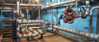
In the first part, “Heating is very simple,” we tried to present as simply as possible the basic information and practical approaches necessary for building simple heating systems. However, “behind the scenes” there were important subtle details of the correct arrangement of the boiler room
(or “furnace room”), issues of calculation and selection of
circulation pumps
, coordinated operation
of boilers
and diverse
consumers
(heating circuits and heated floors,
hot water boiler
, pool heating, etc.). d.).
We hope that everything stated here will help you easily
solve these issues and give you a clear general idea, without complicating it, but simplifying it.
Therefore, perhaps the information will be useful to architects, private developers, construction engineers, installers of heating systems, that is, to all those who are planning or taking part in the construction of a “smart” and economical home. The concept of a primary/secondary
pumped heating system was born in the USA immediately after the Second World War.
This, as well as the idea of using hydronic
boilers with a heat exchanger made of finned copper pipes, was generated by the need for
a practical
solution to the problems of designing heating systems. Over many years of use, such systems have proven their undeniable advantages.
The primary/secondary concept is based on the idea of a transport ring, along which cars can only move in one direction, sometimes turning onto a side (secondary) road. Traffic on the secondary road is two-way, i.e. cars turn onto it from the ring, and again enter the ring (primary). Similar
primary/secondary hydraulic thermal circuits are organized. Under the action of a ring pump, water (coolant) circulates constantly through the primary ring, and when the pumps of the secondary circuits are turned on, it flows into these circuits from the ring, and then returns to the primary ring. Just as the road ring performs the function of a transport interchange, the primary ring in the primary/secondary circuit plays the role of a hydraulic decoupler of the heating system.
On the secondary rings there are heat consumers (radiators, underfloor heating, hot water supply, pool heating, etc.) and heat generators (boilers, heat exchangers, solar panels, etc.). The ring concept makes the system more efficient, less inertial, and quickly responds to heat requests coming from any consumer (zone). Therefore, the use of low-inertia hydronic boilers further improves the speed characteristics of the system as a whole. The application of these two concepts simultaneously enables specialists to offer their customers a reliable and modern solution to their problems.
The use of a primary/secondary system will allow:
Achieve maximum matching between the heat produced and the heat loss of the building to improve indoor comfort
Increase the efficiency of your heating system
Avoid the passage of water through idle boilers (that is, increase the efficiency of the system as a whole)
Quickly and easily carry out repair work on system elements
Today, more than ever, boilers and primary/secondary technology will help heating specialists become highly competitive. Using simple recommendations, you will be able to control the level of comfort in the premises, while significantly increasing the efficiency of the heating system. The directional movement of the coolant in the primary ring provides several strong advantages in heat management and you will most likely use this system with other types of boilers. In addition, you can assemble such a system from standard, easily assembled components. You will find the primary/secondary system much easier to install and set up than any systems you are familiar with.
Some installation features
When designing a system, using information from the Internet and performing installation yourself, remember that a large amount of reading material and watching videos increases your chances of successfully completing what you started.
But the most optimal way to organize heating with your own hands would be to involve, at a minimum, a professional practitioner for consulting support. To ensure high-quality heating of the outermost radiators in the chain, the number of their sections should be increased.
For the gravity version of the system, pipes of significant diameter must be used. And the total length of the circuit should not exceed 30 m.
Installation of the supply main pipe must be carried out at a slight slope. The radiators themselves are installed at the same height and do not at all distort the “geometry” of the room.
Vertical wiring of the “Leningrad” and long “horizontal” will definitely require the introduction of a circulation pump into the system.
When installing a supply pipe deep into the floor with your own hands, you should remember the need to insulate it with heat-insulating roll materials. This will save you significant money during the operation of the system and will not lead to overheating of the “underground” space.
Photo of a needle type tap
Ball valve
Only needle-type valves should be used as shut-off valves on bypasses and auxiliary circuits of the system. They are able to smoothly regulate the flow of liquid through themselves. The use of ball valves is unacceptable here, since they are not intended for “half-open” operation. They are either closed or completely open. Only in these two positions is their long-term performance maintained. There are enough videos on this topic on the Internet.
Concluding a long stream of thoughts, we would like to note that the single-pipe “Leningrad”, which has long been proven over decades of use, with a modern “upgrade” with a circulation pump and control valves on the bypasses, allows you to obtain the advantages of a more complex heating system with its real simplicity and low investment. Ensure its correct installation with your own hands and spend the cold seasons in the warmth and comfort of your private home.
The old problem is solved. (The history of the idea of the primary/secondary system)
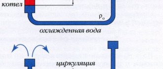
At a time when forced circulation was not yet used in heating, heating system specialists were faced with the following problem:
How to force the flow of water to move in the desired direction if the main driving force is the properties of hot water?
In those years, only natural circulation systems were used. Hot water rises due to the fact that it becomes lighter than cold water. In the case when the flow “turns out to be easier” to rush into the nearest riser, it is almost impossible to force it to move through the radiator. To remain competitive, hydronic heating contractors chose to install single-pipe systems, much like their rival steam heating contractors. But what can make water move through the radiator if the diagram for connecting it to the riser is as follows:
According to the laws of nature, water will rise along the riser as along the path of least resistance. The only way to direct water to the radiator is to increase the hydraulic resistance along the riser. This is exactly what they did before. For this purpose the so-called suction tees
, which created resistance in the riser greater than the resistance in the supply to the radiator.
In such a tee, part of the water is separated from the main flow in the riser and passes through the radiator. It was a simple idea (no mechanical parts), but it required some calculations. For example, the contractor had to know whether to use one or two of these special tees. The answer depended on the diameter of the riser, the size of the radiator and the length of the supply pipes. After much trial and error, contractors came to conclusions about what could and could not be done to solve this problem. By the thirties
, most hydronic heating contractors had moved away from natural circulation systems. Circulation pumps have made it possible to use risers and pipes of much smaller diameters (and much cheaper). But in order for water to pass through the heating devices, they again had to use special separating tees.
Such tees were produced by several companies. The next figure shows a tee with a cone pressed inside. When the flow in the cone narrows, part of the water pressure in the riser is lost. As a result, the radiator is exposed to a pressure difference and water circulates through it. By installing one such tee, the contractor received a certain flow of water through the radiator; by using two, he received a greater flow.
It is clear that without such special tees, the contractor experienced the same problem: Water does not flow through the radiator!
Water always moves along the path of least resistance.
Therefore, for a long time, most contractors used these special tees. And then, quite by accident, a discovery came
.
In the early 1950s, a contractor installed a heating system with suction tees in an office in New York City. Unfortunately, the pipes carrying water from the risers to the radiators were too long, and to his disappointment, he found that there was little water circulation through the radiator, even though he had installed two suction tees - on the supply and return pipes. The reason was that the pressure drop in the supply (due to the large length of the pipes) was greater than the hydraulic resistance along the riser (even with two tees!). The contractor, working in conjunction with the designer and manufacturer of the suction tees, decided to conduct an experiment. He installed small circulation pumps on the radiator lines. He then started these pumps at the same time as the main system pump. To his delight, the radiators heated up very well!
From this discovery there was only one short step to understand that if the “primary” pump (the main pump of the system) works constantly, then it is possible, by periodically turning on and off the “secondary” pumps, to make each radiator an
independent heating zone.
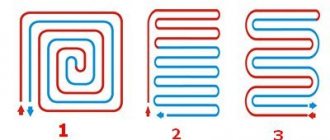
Tichelman ring
When using a Tichelman loop connection, it is necessary to use bottom wiring. Most often it is located in an open position along the walls, but sometimes it is carried out in a hidden way along the floor. Experts offer another installation method: the structure is installed in front of the ceiling, while the communications are covered with a suspended ceiling or in the basement, and the pipe connections are brought to the heating device.
- The heating circuit is installed so that it has the shape of a ring;
- A specific method of connecting the battery is used: if the radiator is the first on the supply pipe, then it will end the return part. The same principle also works in reverse order: the last battery in the supply line will become the first for the reverse.
- If you follow the movement of water in both pipelines, you will notice a single direction. This principle of operation gave the second name to the scheme “passing”.
One of the main advantages of this system is the hydraulic balance, which becomes almost ideal. The coolant is distributed in such a way that it travels the same distance. The design can work using 10 or more radiators with minimal balancing.
Tichelman loop, mounting diagram
Independence of rings in the system
There are no engineering complexities behind the primary/secondary system. You can easily apply such a system to your next job, while experiencing how your competitiveness as a contractor increases. Let's start by looking at this simple piping (primary)
rings.
Nothing complicated.
This is only a single ring system with a circulation pump.
Obviously, if you turn on the pump, all the water leaving the boiler will flow through this ring. The water will circulate because it has no choice. The circulation pump creates a pressure difference and the water moves. It moves and moves in a circle, like a Ferris wheel. And just like in a Ferris wheel, there is no lifting. In a closed system like this, the weight of the water moving up is balanced by the weight of the water moving down. There is no rise of water to a height, only circulation. The circulation pump only works to overcome the resistance of the pipe and boiler.
Let's imagine that we have attached a second
(secondary)
ring to the main one. In this case, we will not install suction tees, which were discussed above, but will install ordinary tees and a valve on the pipe section between the tees.
Will water circulate through the second ring?
This depends on whether the valve is fully open, closed, or in an intermediate position.
The valve plays the role of a gate (or semaphore) that directs water in one direction or another. The valve creates a difference between the resistance of the secondary ring and the resistance of the pipe section between the tees. By increasing or decreasing the resistance value using a valve, we determine the amount of water flow through the second ring. You can get the same effect by using suction tees. They are, in fact, the same valve, having only one, fixed position. The effect of a suction tee can be achieved by using a pipe of a smaller diameter in the area between the tees, because at the same water flow, a pipe of a smaller diameter has greater hydraulic resistance than a pipe of a larger diameter. So everything we're talking about has to do with pressure drop. But none of these methods allows us to easily start, stop or change the volume of water circulation through the second ring. Let's try something else.
We will remove the valve on the pipe section between the tees, and mount a circulation pump
(secondary pump) in the secondary ring.
Now we have something to work with! Our primary pump will work constantly. When the secondary pump is turned off, there will be no water circulation through the secondary ring, because The resistance (pressure drop) along the secondary ring is greater than the pressure drop (resistance) along the section of pipe between the two tees.
But when we turn on the secondary pump, as much water as we need will flow through the second ring, ensuring circulation, because the operation of the secondary pump changes the ratio of pressure drops in the secondary ring.
In the primary/secondary system, the secondary pump draws water from the supply pipe as if the pipe were a boiler. In this sense, the supply pipeline becomes, as it were, an extension of the boiler, from which heat can be taken when and where it is needed
Heat loss through the supply pipeline of the primary ring is minimal because it does not pass through heat exchange zones. Only secondary rings pass through these zones. Both the primary and secondary rings operate completely independently
from each other.
General pipeline section
Installation recommendations
A horizontal single-pipe heating system for a private house will work well with a small number of radiators on one ring branch. Hence the first recommendation: do not plan to install more than five batteries on 1 line, otherwise the last of them will heat very weakly or remain completely cold. In doing so, try to adhere to the following rules:
- If possible, do not use a bottom multi-sided radiator connection, but a diagonal one, so that the coolant passes through the entire device from top to bottom. This will increase its heat transfer;
- Install shut-off ball valves at the inlet to the radiators, and balancing valves at the outlet, with the help of which the system is adjusted after startup;
- choose full bore ball valves;
- If the heat source is a solid fuel boiler, then it must be properly wired. In addition, it is highly advisable to install a buffer tank.
When you need to provide heat to a small two-story house, the following DIY Leningrad scheme can be used:
Note. It is not necessary to install valves on the direct line, as shown in the diagram. Place them at the battery outputs, as described above, and you will be able to successfully balance the system.
In small one-story houses, it is still possible to operate the Leningradka without a pump. For those who decide to assemble it, it is still recommended to install the pump on the bypass. After exiting the boiler, it will be necessary to install a vertical accelerating manifold in order to ensure good flow of coolant into the batteries, as shown in the diagram:
What happens in the pipeline section between the tees
This is important because in traditional (no primary/secondary rings) manifold systems with two pumps running in parallel, where one pump is more powerful than the other, problems sometimes arise. The flow created by a less powerful pump sometimes cannot “enter” the section of the common pipeline through which the flow created by a more powerful pump circulates, due to the difference in pressure that these pumps develop. Here's an example of this:
Two pumps, one developing greater and the other less pressure, have a common section of pipeline in the direction of flow between points A
and
B
(through the boiler).
Let's say a pump with a high pressure is running, and a pump with a lower pressure is turned off. A high-pressure pump creates a lot of pressure at point A
, but when the flow reaches point
B
, the pressure becomes less because part of the pressure created by the pump is actuated by the hydraulic resistance of the pipeline (and the boiler).
The flow “wants”
to move around, through the pipeline of the pump of lower pressure, because water always flows in the direction of least resistance, but in this case the flow will not be able to move this way due to the installed check valve.
Now let's turn on the low-pressure pump. It also develops a certain pressure, but this pressure may not be enough to open the check valve. He is unable to do this only because the pressure difference at points A
and
B
is too big.
The result is a lack of circulation
in the low-pressure pump circuit.
Pros and cons of the Leningrad heating scheme
The main advantages provided by the Leningradka heating system when organizing water heating of a room are: high efficiency, simple installation and maintenance. But unfortunately, such single-pipe heating systems are not without their disadvantages:
- the heating batteries most distant from the boiler in the sequential pipeline circuit should have the maximum number of sections, since the water reaching them through the pipe will be cooled;
- The Leningradka heating system does not provide for the connection of a heated floor or heated towel rail;
- The coolant circulates through the circuit under fairly high pressure.
But this kind of disadvantage is inherent in the traditional single-pipe heating scheme, which does not use elements to regulate the supply of coolant to the radiators. Therefore, installing a bypass with a needle valve on each battery allows you to manually set the temperature of each individual radiator. This made it possible to achieve flexibility and efficiency in adjusting the water heating system.
The improved and modified Leningradka heating system is considered an excellent choice for heating various types of premises. Therefore, its use will help create simple and at the same time effective and inexpensive heating of both a country cottage, a city apartment or a private house.
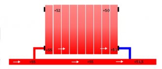
Water flow through a common area
It will be interesting to see what happens in the general section of the pipeline. Depending on the ratio of the powers of the primary and secondary pumps and, accordingly, the amount of water flow created by the primary and secondary pumps, we can make the flow move forward, backward, or not move at all. Here is what it looks like in the pictures:
Let's say we have selected both primary and secondary pumps with a capacity 10
liters/min.
When the secondary pump is not running, the flow rate developed by the primary pump, i.e. 10
/ min will circulate between points
A
and
B. There will be no circulation in the secondary ring.
When the secondary pump is turned on, all water flow will be taken at point A
from the primary ring to the secondary ring.
The water flow through the common section of the pipeline will be zero. This is due to a simple principle: All water entering the tee must exit it. In this case, water has two ways to exit the tee. And which way it goes depends entirely on the secondary pump. Let's now change the conditions
.
Here is an example of a small system. Let's say the productivity of the primary pump is 20
liters/min, and the secondary pump -
10
liters/min.
When the secondary pump is not running, the entire 20
liters/min flow from the primary pump will flow through the common piping section.
Now let's turn on the secondary pump. It will withdraw 10
liters/min through the tee at
point
A. The remaining 10
liters/min will pass through the common section, and at point
B
they will again be joined by the same
10
liters/min that passed through the secondary ring.
The rule “What goes into the tee must come out”
applies.
Only now we have “split”
the existing flow into two directions. We have water flow through the common section of the pipeline, but it is only half the flow that was when the secondary pump was turned off. (What happens in this case is very similar to what happens in a system with suction tees).
But that's not all, because in primary/secondary systems there is another path that water can take along a section of common piping. Let's say we swap the pumps we just used. We will install a pump with a capacity 10
liters/min on the primary, and a pump with a capacity of
20
liters/min on the secondary ring.
Like this: Now look carefully. When the secondary pump is not running, a water flow of 10
liters/min will flow through the common section of the pipeline, because we selected the primary pump with this capacity.
When the secondary pump is turned on, it will begin to withdraw 20
liters/min
A. But how can he do this? 10
flows into this tee. Now again it’s time to remember that simple principle: “Everything that goes into the tee must come out of it.”
But here we can paraphrase it: “Everything that comes out of the tee must go into it.” If we take 20
liters/min through the tee, then the same
20
liters/min should enter it from the other two sides.
Because The primary pump provides only 10
liters/min, the secondary pump must take the missing
10
liters/min from the opposite side of the tee.
In other words, take them out of your own circulation flow. In this case, when both pumps are running, water will move along the common section of the pipeline in the opposite direction. Just think about the possibilities available! You can mix return water with the supply water and create a two-temperature
system (without using three-way taps), if you require it.
The primary/secondary system provides you with a lot of possibilities, if, of course, you have the desire to work with your head and hands. Consider, for example, what can be achieved by applying this technique to boiler systems. Main components of the heating system
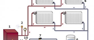
How to make two-pipe heating in a private house
The choice of a suitable two-pipe scheme depends on the area of the house, its number of storeys, power outages, and financial capabilities:
- If the power in the house is often turned off, and the owners do not plan to purchase a generator, it is better to opt for a gravitational open heating system.
- For self-installation, a double-circuit shoulder design is suitable. It works even with small errors.
- For modern houses, collector options are often chosen. Communications can be hidden in wall cabinets and under floor screeds, and combs can be closed in a manifold cabinet. Despite the apparent complexity, home craftsmen install beam circuits on their own. There are many instructions on the Internet on how to do this.
- For buildings with large rooms, it is better to choose the Tichelman ring. Its elements can also be hidden under the floor. But such a thermal design will not be cheap.
Hydronic boilers
Evie Lewis Miller, a Californian engineer and inventor, came up with the idea of creating high-speed
,
small-volume
boilers with a heat exchanger made of straight copper finned tubes in
1946
. He was confident that the application of this idea would eliminate the processes of scale formation and electrolytic corrosion, which significantly reduce the service life of boilers with cast iron sectional and steel tubular heat exchangers when they are used in water heating systems. During those post-war years, the Southern California pool equipment industry was in its infancy, and Evie Miller's boilers proved ideal for use as pool water heaters. His boilers, in most cases, were installed in the open air, being exposed to all sorts of influences. They worked on highly chlorinated water with a high oxygen content. They worked in conditions that were incomparably worse than those in which any hot water heating boiler operates. And they worked for many years. Given their extreme operating conditions with chlorinated, oxygenated swimming pool water, it seemed natural to apply these boilers to hydronic heating systems as they were continually improved throughout the 50s.
Final Conclusion
Practice shows that a 2-pipe dead-end system is suitable for heating most average-sized residential buildings. The technical solution impresses with its simplicity and reasonable cost of installation work. Collector and associated wiring will be more expensive - the price of the equipment and the length of the lines play a role. Take a look at the Tichelman loop diagram - distribution pipelines of the same diameter run along the entire perimeter of the building.
A separate discussion is a two-pipe heating system with natural water circulation. In conditions of frequent power outages, it is better not to take risks and not to chase the beauty of the interiors, but to install energy-independent heating. The high initial investment is offset by heat and low electricity consumption.
Two small ones are better than one big one
Now think about this: on any other day of the year, the boiler is capable of producing much more heat than required.
Does it make sense that the boiler operates at full capacity on days when the outside temperature is 0 or +5°C?
Of course not. It is on such less cold days that boilers connected according to the primary/secondary system principle will show their advantage, because they will produce exactly as much heat as is necessary to compensate for the heat loss of the building at the moment. This gives you two advantages that you can use to your customer's advantage: comfort and savings. This gives you a better argument than your competitors. For example, the total heat demand of a building (heating plus hot water supply) is 150
kW.
You can choose one boiler of this performance. It will provide heat and hot water to the building any day of the year, but for most days of the year its power will be too large. However, by distributing the required productivity between two boilers, say, 75
kW each, you will simultaneously solve several problems:
First, by sharing the load, you recognized that not every day of the year is the coldest day.
On “average” days of the heating season, only one boiler will operate, while producing enough heat for heating.
Because the output of this smaller boiler is closer to the actual heat loss of the building on such "average" days, the duty cycles of the small boiler will be longer than that of a single double capacity boiler. By using two smaller boilers, overall operating efficiency is significantly improved by reducing hot standby
(i.e. losses caused by natural cooling of an idle boiler).
This also reduces fuel costs. Naturally, as the weather gets colder, a second boiler in series will come into operation to help the first maintain the required temperature in the primary ring. In other words, these two small boilers will work like one big one, but only on the coldest days.
Secondly, by installing two boilers, you get a wonderful advantage that is missing in the case of one large boiler.
The likelihood that both boilers will need repair at the same time is very low. This important feature is the reason that this type of system is used in hospitals, schools, and kindergartens. It is simply impossible to allow them to remain without heat.
Thirdly, by connecting boilers according to the primary/secondary system principle, you will prevent water from passing through an idle boiler.
This means that you will reduce heat loss through the structure and lining of the boiler. A working boiler will produce the heat required by the system, and a switched-off boiler will be, as it were, cut off from the system by valves, although in fact there are no valves. This advantage, combined with the low-capacity boiler design, further increases the overall efficiency of the system.
But that's not all.
Let's take it up another level by adding the
EM 2
.
This simple and inexpensive device keeps the boiler's secondary circulation pump running for several minutes after the boiler's main burners have switched off. The pump thereby removes excess heat from the copper heat exchanger and transfers it to the primary ring. At the same time, EM 2 completely eliminates boiler losses in hot reserve.
When boilers operate in a primary/secondary system, you can distribute the total load across more than two boilers if required.
However
, we have concluded that the maximum number of boilers that can be recommended for effective use in a primary/secondary system is
four
. The reason is simple: the economic benefit of installing more than four boilers is so small that it does not justify the additional installation effort.
But imagine the capabilities of four boilers combined into a primary/secondary system, each of which can switch from maximum power (100%) to reduced power (50%) and back again. You can have four boilers, sensitively responding to the heat needs of the system and distributing the loads of this system among themselves. The burners of one or two boilers can operate at maximum power, while the burners of the third boiler operate at half power, and the fourth boiler is switched off at this time and is in reserve.
Using this strategy, you have the opportunity to “fine-tune”
systems for heat and hot water needs for every day of the year.
You get two advantages at once: comfort and savings.
The boiler piping is easy to install. You can install either a small domestic system or a large multi-boiler primary/secondary system. It is so simple!
Dead-end heating branches
This scheme can be seen in cottages and country houses. Now such a system has begun to be used in high-rise buildings. In this case, the network consisting of radiators is presented in the form of several two-pipe branches. The coolant also flows along one part towards the battery, and through the other - back to the boiler. The work itself occurs due to the circulation pump, which is placed near the boiler. The average pressure in the entire structure is 1-2.5 bar. To compensate for the expansion of the liquid, the unit contains a membrane tank - it is installed in the boiler room. You can see the insertion point in front of the circulation pump. There are also additional elements for getting rid of excess air: Mayevsky cranes and a safety group are used. The design contains a pressure gauge to monitor the pressure status and a safety valve. Here, the bottom horizontal wiring is most often used: both pipes are mounted under the radiator in an open manner.
Dead-end heating branches