Sep 8
Our service department regularly receives questions related to expense imbalances. The larger the heating station, the more noticeable the problem of non-convergence of meter readings.
For example, the amount of thermal energy is calculated using the formula for an open system:
The formula includes the difference in flow rates on the supply and return pipelines (G1-G2). If there are no leaks or water intake from the system, then it is logical to expect that the return flow rate will coincide with the supply flow rate and their difference will be equal to zero. In practice, this often turns out not to be the case, and this situation is considered a variant of the norm. This is explained by the standard error of metering devices, which are absolutely in good working order and suitable for use based on the results of verification.
So where do “non-conformities” come from and what to do with them?
By law, the flow meter can be mistaken by no more than 2%. When the formula uses the difference or addition of two expenses with their own errors, then their errors also add up (modulo).
|±2%|+|±2%|=|±4%|
For example , there is a flow rate of 100 m3/h, a device with an error of 2% can show you 102 m3/h or 98 m3/h and this is the norm. If two flow meters measure this flow and both receive 102 m3/h or 98 m3/h, then the difference in their readings will indeed be zero, but during the reporting period, water meters make many measurements and, of course, cannot “make mistakes in one direction” all the time. Therefore, for our example, it is acceptable when the supply flow meter shows 102 m3/h, and the return flow meter shows 98 m3/h. The difference in flow rates is 4 m3/h, and this is the norm.
There is no need to pay for this 4% difference, because... such water losses are considered an error in the device, and consumption exceeding 4% must be paid, because this water has clearly been withdrawn from the system by the consumer or there is a leak.
What should be the difference between supply and return?
The minimum temperature of the coolant should be 70 C in the supply, 50 C in the return. And somewhere when the AVERAGE TEMPERATURE of the outside air is reached and in the direction of increasing negative values of the outside temperature, the temperature in the supply should increase.
Interesting materials:
How to fit text into a Powerpoint shape? How to enter text into a cell? How to always hit darts? How to insert an Excel graph into a presentation? How to insert an image in Excel? How to insert a picture from Google into Word? How to insert a picture into a presentation 2003? How to insert music into Tik Tok not first? How to insert the required number of columns in Excel? How to insert a slide into Google Slides?
Practical workers involved in the maintenance and operation of heat meters based on high-speed flow meters (electromagnetic, ultrasonic, differential pressure meters), in which the flow rate is determined by integrating the speed of the coolant in the pipeline, have already noticed that heat meters located at the outlet are both closed and and open heat supply systems, can show a coolant flow rate that exceeds the inlet flow rate. This can only happen due to an increase in the volumetric velocity of the coolant at the outlet.
One of the reasons for the increase in output speed is the presence of a gas phase (air) in the coolant.
Below we analyze the influence of the gas phase (G) of the coolant on the change in the instantaneous value of the volumetric flow rate (Q) at the outlet of a closed heat supply system depending on the pressure (P) and temperature (T) at the inlet and outlet of the system. In real conditions, water contains a certain amount of the gas phase (air) in the form of microbubbles. The sizes of microbubbles vary widely from 10-6 mm to 1 mm or more. Air microbubbles of minimal size (10-6... 10-3) mm have significant stability and are difficult to degas. The usual air content in water varies widely: from 10-3% (degassed water in special closed vessels) to 5% or more with forced circulation of water in pipeline water and heat supply systems.
The main source of air entering pipeline systems is suction through leaks in the suction sections of circulation pumps. In pipeline systems with poor quality seals, the volumetric air content in water can be quite significant - 10% or more.
The volumetric content of the gas phase (air) in a liquid changes with changes in pressure and temperature in accordance with the Clapeyron equation:
| (1) |
where P0, TO - absolute pressure and absolute temperature [K] in the initial section of the pipeline (at the system inlet);
P1, T1 - absolute pressure and absolute temperature in the final section of the pipeline (at the system outlet);
Уr(Т0, Р0), Уr(Т1, Р1) - volumetric content of the gas phase (undissolved air) in the liquid, respectively, at temperatures and pressures Т0, Р0 and Т1,Р1.
If we denote Ur(T0. P0)=Ug0 , and Ur(T1, P1)=Ur1 , then the volumetric flow rate of the pumped medium at the inlet (Q0) of the system and at the output (Q1) of the system can be represented in this form:
| (2) | |
| (3) |
where Ql is the volumetric flow rate of liquid (water) without the air contained in it.
The volumetric flow rate of liquid Ql is an almost constant value if we neglect the slight change in the volume of water with changes in pressure and temperature. The value of Vr1 , as can be seen from (1) , changes significantly with changes in temperature and pressure, which leads to a change in the volumetric flow rate of the pumped medium at the outlet of the system. Taking into account (2) and (3), the relative change in the volumetric flow rate dQ of the pumped medium at the outlet of a closed system can be represented in the following form:
| (4) |
Taking into account (1) , expression (4) will look like:
| (5) |
As can be seen from (5) , the main influence on the relative change dQ of the volumetric flow rate at the outlet will be exerted by the expression in square brackets. Therefore, we transform its first term by introducing the concept of pressure loss DP :
| (6) |
Expressing the absolute temperature in terms of the water temperature at the inlet (t0) and outlet (t1) in degrees Celsius: T0 = 273 + t0; T1= 273 + t1 . Then it will look like:
| (7) |
where dP - DP/P0 - relative pressure loss in the system.
I use the Maclaurin series expansion in powers of small magnitude ( 1/( 1+-x) = 1-+x) , expression (7) can be represented as:
| (8) |
where Dt = t0 - tl is the temperature difference at the inlet and outlet of the system.
Multiplying the brackets of expression (8) and neglecting small second-order ones t0*t1/(273*273) and dP*Dt/273 , we can (8) in the form:
| (9) |
Substituting (9) into expression (5) we can obtain a simple formula for determining the relative change in volumetric flow rate at the output of a closed heat supply system:
| (10) |
As can be seen from (10), the relative change in the volume flow rate at the outlet is directly proportional to the volumetric air content in the coolant, and the volume flow rate at the outlet itself can be either greater or less than the input one. According to expression (10) for 10% volumetric air content in the coolant, taking into account the real pressure loss DP (1.5...3 atm), inlet pressure (4...6 atm) and temperature difference (30°C...40°C ) a table has been compiled depending on the relative change in the volumetric flow rate of the coolant at the outlet of a closed system on the relative pressure loss dP = DP/P0 and the temperature difference Dt at 10% volumetric air content in the coolant.
| dP | Relative change in volume flow, %, at Dt, °С | ||||||
| 10 | 20 | 30 | 40 | 60 | 80 | 100 | |
| 0,10 | 0,6 | 0,3 | -0,1 | -0,5 | -1,1 | -1,7 | -2,5 |
| 0,25 | 1,9 | 1,6 | 1,4 | 0,9 | 0,3 | -0,4 | -1,1 |
| 0,35 | 2,8 | 2,6 | 2,3 | 1,8 | 1,2 | 0,6 | -0,2 |
| 0,50 | 4,2 | 3,9 | 3,6 | 3,2 | 2,6 | 1,9 | 1,2 |
| 0,60 | 5,1 | 4,8 | 4,5 | 4,1 | 3,5 | 2,8 | 2,1 |
| 0,75 | 6,5 | 6,1 | 5,9 | 5,5 | 4,8 | 4,2 | 3,5 |
As can be seen from the table, for real relative pressure losses (0.25.-0.75) and temperature difference at the inlet and outlet (30TC), the increase in volume flow at the outlet can range from 1.5% to 6%.
Authors:
Abarinov Evgeniy Georgievich, professor of the Department of Industrial Electronics, Gomel State Technical University (GGTU) named after. BY. Sukhoi, contact tel., E-mail: This email address is being protected from spambots. Javascript must be enabled in your browser to view the address.
Mikhnevich Anatoly Vasilievich, Associate Professor of the Department of Hydropneumoautomatics, GGTU named after. BY. Sukhoi, Belarus, 246746, Gomel, October Avenue 48, GGTU named after. BY. Sukhoi, fax (0232)47-91-65.
Krushev Vladimir Leonidovich, leading engineer of KP "Belavtomatikaservis", contact tel. f Belarus, 246041, Gomely ud. Karbysheva 12, fax.
Two-pipe circuit in a private house
First, let's generalize a little. Let’s take, for example, calculating the diameter of polypropylene pipes for heating in a private house. Basically, products with a cross section of 25 mm are used for the circuit, and bends to radiators are set to 20 mm. Due to the fact that the size of the heating pipes in a private house, used as pipes to the batteries, is smaller, the following processes occur:
- the coolant speed increases;
- circulation in the radiator improves;
- The battery warms up evenly, which is important when connected at the bottom.
Types of heating schemes
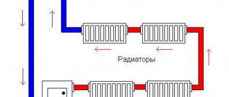
For multi-storey buildings, a single-pipe direct distribution system is often used. It does not have a clear division of pipes into the liquid supply to the radiators and the return, so the complete circuit is conventionally divided into two equal parts. The riser coming out of the boiler is called the supply, and the pipes coming out of the last radiator are called the return. Advantages of this scheme:
- saving time and material costs;
- convenience and simplicity of installation work;
- aesthetic appearance;
- the absence of a return riser and a sequential arrangement of radiators (coolant is supplied to the 1st, then the 2nd, 3rd and so on ).
For a single-pipe system, vertical wiring with a vertical circuit and heat supply from above is common.
With a two-pipe wiring system, it is meant to install two closed, parallel-connected circuits, one of them provides the function of supplying coolant to the heating device (radiator), the second - the function of its outlet (return).
Radiators are connected in several ways:
- Lower (or saddle, crescent-shaped). Provides for connection of supply and return to the lower connecting holes of the radiator. A Mayevsky tap and a plug are installed on the upper holes. Used for systems in which pipes are hidden under the floor or baseboard. Suitable for multi-section radiators; with a small number of sections, heat loss reaches up to 15%.
- The lateral method is popular. The pipes are connected to the radiator on one side: coolant supply through the top, return through the bottom. Not suitable for devices with a large number of sections.
What could be the consequences: narrowing the diameter of the heating pipe
Narrowing the pipe diameter is extremely undesirable. When wiring around the house, it is recommended to use the same standard size - there is no need to increase or decrease it. The only possible exception would be a large length of the circulation circuit. But even in this case you need to be careful.
Many experts do not recommend narrowing the diameter of the pipes, as this can have a detrimental effect on the entire heating system
But why does the size become smaller when replacing a steel pipe with a plastic one? Everything is simple here: with the same internal diameter, the outer diameter of the plastic pipes themselves is larger. This means that the holes in the walls and ceilings will have to be expanded, and seriously - from 25 to 32 mm. But for this you will need a special tool. Therefore, it is easier to pass thinner pipes into these holes.
But in this same situation, it turns out that the residents who made such a replacement of pipes automatically “stole” approximately 40% of the heat and water passing through the pipes from their neighbors in this riser. Therefore, it is worth understanding that the thickness of pipes that are arbitrarily replaced in a heating system is not a matter of private decision; this cannot be done. If steel pipes are replaced with plastic ones, no matter how you look at it, you will have to widen the holes in the ceilings.
There is such an option in this situation. When replacing risers, you can pass new pieces of steel pipes of the same diameter into the old holes; their length will be 50-60 cm (this depends on such a parameter as the thickness of the ceiling). And then they are connected with couplings to plastic pipes. This option is quite acceptable.
Adjustable throttle washer
Any organization that operates a heat supply system must be able to carry out adjustments. There are several basic steps to carry out this operation, as well as one important element - the throttle washer.
Step one. Calculations
It is worth noting that there are no two identical heat supply systems. However, certain patterns were noticed that are repeated when setting up the thermal system. The first step in more than 90% of cases is the moment of hydraulic calculation. There are several options for performing this operation.
Option 1. Manual calculation option. In this case, it is necessary to have all the necessary reference literature on hand, and the calculation is carried out step by step on each required section of the network. If an incorrect answer occurs on any segment, then it is necessary to change the parameters and carry out the computational work again. The main disadvantage of this work is the long turnaround time, and the process itself is very labor-intensive.
Option 2. An expensive electronic computer is purchased, which is capable of performing all calculations accurately and quickly. It only takes some time to study it, and then the necessary parameters are simply entered.
Option 3. Currently, there are organizations that provide services specifically for calculating all the necessary network parameters.
Step two. Readiness
At the second stage, it is necessary to determine whether the thermal system is ready for adjustment. In order to carry out this step, it is necessary to resort to installing a throttle washer. There are several types of installation.
The first option is based on the fact that the company does not rely too much on the calculations carried out and the results obtained. In this case, the washers are installed in some places that need to be checked. It is worth noting here that the diameter for each device will be rounded. Moreover, rounding will occur towards the drill with the largest diameter. However, experts say that this method is terribly ineffective. It's best not to use it at all.
Installation of washers
There are two other verification methods.
Optimal values in an individual heating system
H2_2
Autonomous heating helps to avoid many problems that arise with a centralized network, and the optimal temperature of the coolant can be adjusted according to the season. In the case of individual heating, the concept of standards includes the heat transfer of a heating device per unit area of the room where this device is located. The thermal regime in this situation is ensured by the design features of the heating devices.
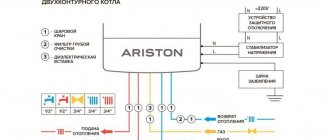
It is important to ensure that the coolant in the network does not cool below 70 °C. The optimal temperature is considered to be 80 °C. With a gas boiler, it is easier to control heating, because manufacturers limit the ability to heat the coolant to 90 °C. Using sensors to regulate the gas supply, the heating of the coolant can be adjusted.
It is a little more difficult with solid fuel devices; they do not regulate the heating of the liquid, and can easily turn it into steam. And it is impossible to reduce the heat from coal or wood by turning the knob in such a situation. Control of heating of the coolant is quite conditional with high errors and is carried out by rotary thermostats and mechanical dampers.
Electric boilers allow you to smoothly regulate the heating of the coolant from 30 to 90 °C. They are equipped with an excellent overheat protection system.