Due to its ease of installation, low cost and sufficient efficiency, the open heating system continues to be in demand. Once you understand the principle of operation, equipment and installation rules, you will be able to organize the heat supply to your home yourself.
We will tell you how to create a workable open-type heating circuit. We will show you how to build a system, strictly following technological requirements and standards when selecting and connecting elements. Taking into account our recommendations, you will build a trouble-free, efficient circuit.
We offer independent craftsmen to familiarize themselves with practice-tested assembly options. The information presented for consideration is supplemented with useful diagrams, photo collections, and video instructions.
Closed system diagrams
The following types of wiring are used for heating country and country houses:
- Single-pipe. All radiators are connected to a single main line running along the perimeter of the room or building. Since the hot and cooled coolant move through the same pipe, each subsequent battery receives less heat than the previous one.
- Two-pipe. Here, heated water enters the heating devices through one line and leaves through the second. The most common and reliable option for any residential buildings.
- Passing (Tichelman loop). Same as two-pipe, only the cooled water flows in the same direction as the hot water, rather than returning in the opposite direction (shown in the diagram below).
- Collector or beam. Each battery receives coolant through a separate pipeline connected to a common comb.
Single-pipe horizontal distribution (Leningrad)
The single-pipe horizontal scheme justifies itself in one-story houses with a small area (up to 100 m²), where heating is provided by 4-5 radiators. You should not connect more to one branch, the last batteries will be too cold. The option with vertical risers is suitable for a building of 2-3 floors, but during the implementation process it will be necessary to go through ceiling pipes in almost every room.
Single-pipe scheme with top distribution and vertical risers
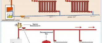
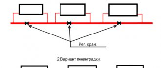
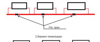
The two-pipe circuit with dead-end branches (shown at the beginning of the article) is quite simple, reliable and definitely recommended for use. If you are the owner of a cottage with an area of up to 200 m² and a height of 2 floors, then lay out the mains using pipes with a flow area of DN 15 and 20 (external diameter - 20 and 25 mm), and to connect radiators, use DN 10 (external diameter - 16 mm).
Associated pattern of water movement (Tichelman loop)
The Tichelman loop is the most hydraulically balanced, but more difficult to install. The pipelines will have to be laid around the perimeter of the rooms or the entire house and pass under the doors. In fact, a “hitch ride” will cost more than a two-pipe one, but the result will be approximately the same.
The beam system is also simple and reliable, in addition, all wiring is successfully hidden in the floor. The connection of nearby batteries to the comb is carried out with 16 mm pipes, and the remote ones with 20 mm pipes. The diameter of the line from the boiler is 25 mm (DN 20). The disadvantage of this option is the price of the collector unit and the complexity of installation with the laying of highways when the floor covering is already done.
Scheme with individual connection of batteries to the collector
Comparison by installation price
Supporters of single-pipe heating networks like to remind people of the low cost of this type of wiring. The reduction in costs compared to a two-pipe scheme is justified by half the number of pipes. We claim the following: “Leningradka” will cost less than a dead-end system in one case - if you solder the heating from polypropylene.
Let's prove our statement with calculations - let's take as an example a one-story dwelling measuring 10 x 10 m = 100 m² (in plan). Let's put the "Leningrad" layout on the drawing, count the fittings with pipes, then make a similar estimate for the dead-end wiring.
A common return manifold running through the corridor allows the ring line to remain small in diameter. If it is removed, the cross-section of the pipes will increase to Ø25 mm (internal)
So, to install one-pipe heating you will need:
- pipe DN20 to the collector (outside Ø25 mm) – 40 m;
- tr. DN25 Ø32 mm for return – 10 m;
- tr. DN10 Ø16 mm for connections – 8 m;
- tee 25 x 25 x 16 (outer size) – 16 pieces;
- tee 25 x 25 x 20 – 1 pc.
Reference. There is no need to make a return jumper along the corridor. Then for 9 radiators it will be necessary to increase the cross-section of the ring main to the size of DN25 (outer - 32 mm).
Based on the following layout, we will find out the need for pipes and fittings for a two-pipe network:
- tr. DN15 Ø20 mm – 68 meters (mains);
- tr. DN10 Ø16 mm – 22 m (radiator connections);
- tee 20 x 20 x 16 mm – 16 pcs.
Now we will find current prices for plumbing fittings and pipes made of 3 materials: reinforced polypropylene PP-R, metal-plastic PEX-AL-PEX and cross-linked polyethylene PEX from well-known manufacturers. Let's put the calculation results in the table:
Note. We do not take into account the cost of batteries, radiator taps and installation of a single-pipe “Leningrad” - let’s assume that you assemble the system with your own hands. The cost is determined in Russian rubles, but this fact does not play a special role; the price ratio will remain the same for any country.
As you can see, the costs for polypropylene tees and pipes are almost the same for both schemes - the shoulder scheme turned out to be only 330 rubles more expensive. For other materials, two-pipe wiring definitely wins. The reason lies in the diameters - the prices of larger cross-section pipes increase sharply compared to the “running” sizes of 16 and 20 mm.
You can take cheaper plumbing fixtures from other manufacturers and perform the calculation - the ratio is unlikely to change. Note that we skipped the 90° elbows for pipe turns and other small items, since we do not know the exact quantity. If you carefully calculate all the materials, the cost of the Leningradka will increase even more. An expert demonstrating calculations on video came to similar conclusions:
The principle of operation of the system with duress
A circulation pump is a small electrical device that is extremely simple. There is an impeller inside the housing; it rotates and gives the coolant circulating through the system the necessary acceleration. The electric motor that provides rotation consumes very little electricity, only 60-100 W.
The presence of such a device in the system greatly simplifies its design and installation. Forced circulation of the coolant allows the use of small-diameter heating pipes and expands the possibilities when choosing a heating boiler and radiators.
Very often, a system originally created with natural circulation in mind does not work satisfactorily due to the low speed of coolant movement through the pipes, i.e. low circulation pressure. In this case, installing a pump will help solve the problem.
However, you should not get too carried away with the speed of water in the pipes, since it should not be excessively high. Otherwise, over time, the structure may simply not withstand additional pressure for which it is not designed.
If in systems with natural coolant circulation an open expansion tank can be used, then in forced circuits preference should be given to a closed, sealed container
For residential premises, the following maximum speed limits for coolant movement are recommended:
- with a nominal pipe diameter of 10 mm – up to 1.5 m/s;
- with a nominal pipe diameter of 15 mm - up to 1.2 m/s;
- with a nominal pipe diameter of 20 mm or more - up to 1.0 m/s;
- for utility rooms of residential buildings - up to 1.5 m/s;
- for auxiliary buildings – up to 2.0 m/s.
In systems with natural circulation, the expansion tank is usually placed on the supply side. But if the design is supplemented with a circulation pump, it is usually recommended to move the storage tank to the return line.
The design of the circulation pump is very simple; the task of this device is to give the coolant an acceleration sufficient to overcome the hydrostatic resistance of the system
In addition, instead of an open tank, you should install a closed one. Only in a small apartment, where the heating system is short and has a simple structure, can you do without such a rearrangement and use the old expansion tank.
Where to put
It is recommended to install a circulation pump after the boiler, before the first branch, but on the supply or return pipeline it doesn’t matter. Modern units are made from materials that can withstand temperatures up to 100-115°C. There are few heating systems that work with a hotter coolant, so considerations of a more “comfortable” temperature are untenable, but if you feel safer, put it in the return line.
Can be installed in the return or direct pipeline after/before the boiler up to the first branch
There is no difference in hydraulics - the boiler, and the rest of the system; it makes absolutely no difference whether there is a pump in the supply or return branch. What matters is the correct installation, in terms of strapping, and the correct orientation of the rotor in space
Nothing else matters
There is one important point regarding the installation location. If the heating system has two separate branches - on the right and left wings of the house or on the first and second floor - it makes sense to install a separate unit on each, and not one common one - directly after the boiler. Moreover, the same rule remains on these branches: immediately after the boiler, before the first branch in this heating circuit. This will make it possible to set the required thermal conditions in each part of the house independently of the other, and also in two-story houses to save on heating. How? Due to the fact that the second floor is usually much warmer than the first floor and much less heat is required there. If there are two pumps in the branch that goes up, the speed of movement of the coolant is set much lower, and this allows you to burn less fuel, without compromising the comfort of living.
There are two types of heating systems - forced and natural circulation. Systems with forced circulation cannot work without a pump; systems with natural circulation work, but in this mode they have lower heat transfer. However, less heat is still much better than no heat at all, so in areas where electricity is often cut off, the system is designed as hydraulic (with natural circulation), and then a pump is installed into it. This gives high heating efficiency and reliability. It is clear that the installation of a circulation pump in these systems is different.
All heating systems with heated floors are forced - without a pump, the coolant will not pass through such large circuits
Forced circulation
Since a forced circulation heating system without a pump is inoperative, it is installed directly into the gap in the supply or return pipe (of your choice).
Most problems with the circulation pump arise due to the presence of mechanical impurities (sand, other abrasive particles) in the coolant. They can jam the impeller and stop the motor. Therefore, a mesh dirt filter must be placed in front of the unit.
Installing a circulation pump in a forced circulation system
It is also advisable to install ball valves on both sides. They will make it possible to replace or repair the device without draining the coolant from the system. Turn off the taps and remove the unit. Only that part of the water that was directly in this piece of the system is drained.
Natural circulation
The piping of the circulation pump in gravity systems has one significant difference - a bypass is required. This is a jumper that makes the system operational when the pump is not working. One ball shut-off valve is installed on the bypass, which is closed the entire time the pumping is running. In this mode, the system operates as forced.
Installation diagram of a circulation pump in a system with natural circulation
When the electricity goes out or the unit fails, the valve on the jumper is opened, the valve leading to the pump is closed, and the system operates as a gravity system.
Installation features
There is one important point, without which the installation of the circulation pump will require rework: it is necessary to rotate the rotor so that it is directed horizontally. The second point is the direction of flow. There is an arrow on the body indicating which direction the coolant should flow. This is how you turn the unit so that the direction of movement of the coolant is “in the direction of the arrow”.
The pump itself can be installed both horizontally and vertically, just when selecting a model, make sure that it can work in both positions. And one more thing: with a vertical arrangement, the power (pressure created) drops by about 30%. This must be taken into account when choosing a model.
Expansion tank for closed heating system
The expansion tank is designed to compensate for changes in coolant volume depending on temperature. In closed heating systems, this is a sealed container divided into two parts by an elastic membrane. At the top there is air or inert gas (in expensive models). While the coolant temperature is low, the tank remains empty, the membrane is straightened (picture on the right).
Operating principle of a membrane expansion tank
When heated, the coolant increases in volume, its excess rises into the tank, pushing back the membrane and compressing the gas pumped into the upper part (in the picture on the left). This is displayed on the pressure gauge as an increase in pressure and can serve as a signal to reduce the combustion intensity. Some models have a safety valve that releases excess air/gas when a threshold pressure is reached.
As the coolant cools, the pressure in the upper part of the tank squeezes the coolant out of the container into the system, and the pressure gauge readings return to normal. That's the whole principle of operation of a membrane-type expansion tank. By the way, there are two types of membranes - disc-shaped and pear-shaped. The shape of the membrane does not affect the operating principle in any way.
Types of membranes for expansion tanks in closed systems
Volume calculation
According to generally accepted standards, the volume of the expansion tank should be 10% of the total coolant volume. This means that you must calculate how much water will fit in the pipes and radiators of your system (it is in the technical data for radiators, and the volume of the pipes can be calculated). 1/10 of this figure will be the volume of the required expansion tank. But this figure is only valid if the coolant is water. If non-freezing liquid is used, the tank size is increased by 50% of the calculated volume.
Here is an example of calculating the volume of a membrane tank for a closed heating system:
- the volume of the heating system is 28 liters;
- expansion tank size for a system filled with water 2.8 liters;
- the size of the membrane tank for a system with non-freezing liquid is 2.8 + 0.5 * 2.8 = 4.2 liters.
When purchasing, select the nearest larger volume. Don't take less - it's better to have a small supply.
What to look for when purchasing
There are red and blue cans in stores. Red tanks are suitable for heating. The blue ones are structurally the same, only they are designed for cold water and cannot tolerate high temperatures.
What else should you pay attention to? There are two types of tanks - with a replaceable membrane (they are also called flanged) and with a non-replaceable one. The second option is cheaper, and significantly, but if the membrane is damaged, you will have to buy the whole thing
For flanged models, only the membrane is purchased.
Place for installing a membrane type expansion tank
Usually they place an expansion tank on the return pipeline in front of the circulation pump (if you look in the direction of flow of the coolant). A tee is installed in the pipeline, a small section of pipe is connected to one part of it, and an expander is connected to it through fittings. It is better to place it at some distance from the pump so that pressure differences are not created. An important point is that the piping section of the membrane tank must be straight.
Installation diagram of an expansion tank for membrane-type heating
A ball valve is installed after the tee. It is necessary to be able to remove the tank without draining the coolant. It is more convenient to connect the container itself using an American nut. This again makes installation/disassembly easier.
The empty device does not weigh much, but when filled with water it has a significant mass. Therefore, it is necessary to provide a method of mounting on the wall or additional supports.
Security group
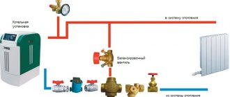
A safety group is placed on the supply pipeline at the outlet of the boiler. She must control its operation and system parameters. Consists of a pressure gauge, automatic air vent and safety valve.
The boiler safety group is placed on the supply pipeline before the first branch
The pressure gauge makes it possible to control the pressure in the system. According to recommendations, it should be in the range of 1.5-3 Bar (in one-story houses it is 1.5-2 Bar, in two-story houses it is up to 3 Bar). If you deviate from these parameters, appropriate measures must be taken. If the pressure drops below normal, you need to check if there are any leaks, and then add some coolant to the system. At increased pressure, everything is somewhat more complicated: it is necessary to check in what mode the boiler is operating, whether it has overheated the coolant. The operation of the circulation pump, the correct operation of the pressure gauge and the safety valve are also checked. It is he who must discharge excess coolant when the threshold pressure value is exceeded. A pipe/hose is connected to the free branch pipe of the safety valve, which is discharged into the sewer or drainage system. Here it is better to do it in such a way that it is possible to control whether the valve works - if water is discharged frequently, you need to look for the reasons and eliminate them.
Security group composition
The third element of the group is an automatic air vent. Air trapped in the system is removed through it. A very convenient device that allows you to get rid of the problem of air locks in the system.
Security groups are sold assembled (pictured above), or you can buy all the devices separately and connect them using the same pipes that were used to wire the system.
Differences between open and closed heating systems
There are the following distinctive features of open and closed heating systems:
According to the location of the expansion tank. In an open heating system, the tank is located at the highest point of the system, and in a closed system, the expansion tank can be installed anywhere, even next to the boiler. The closed heating system is isolated from atmospheric flows, which prevents air from entering. This increases service life. By creating additional pressure in the upper components of the system, the possibility of the formation of air locks in radiators located on top is reduced. An open heating system uses pipes with a large diameter, which creates inconvenience, and the installation of pipes is carried out at an angle to ensure circulation. It is not always possible to hide thick-walled pipes
To ensure all hydraulic rules, it is necessary to take into account the slopes of flow distribution, lifting heights, turns, narrowing, and connections to radiators. A closed heating system uses smaller diameter pipes, which reduces the cost of the design. Also, in a closed heating system, it is important to install the pump correctly to avoid noise.
Advantages of an open heating system
- easy system maintenance;
- the absence of a pump ensures silent operation;
- uniform heating of the heated room;
- quick start and stop of the system;
- independence from power supply, if there is no electricity in the house, the system will be operational;
- high reliability;
- no special skills are required to install the system; first of all, the boiler is installed; the power of the boiler will depend on the heated area.
Disadvantages of an open heating system
- the possibility of reducing the service life of the system if air enters, as heat transfer decreases, resulting in corrosion, water circulation is disrupted, and air pockets form;
- air contained in an open heating system can cause cavitation, which destroys system elements located in the cavitation zone, such as fittings and pipe surfaces;
- the possibility of freezing of the coolant in the expansion tank;
- slow heating of the system after switching on;
- constant monitoring of the coolant level in the expansion tank is necessary to prevent evaporation;
- impossibility of using antifreeze as a coolant;
- quite bulky;
- low efficiency.
Advantages of a closed heating system
- simple installation;
- there is no need to constantly monitor the coolant level;
- the ability to use antifreeze without fear of defrosting the heating system;
- by increasing or decreasing the amount of coolant supplied to the system, you can regulate the temperature in the room;
- due to the absence of water evaporation, the need to replenish it from external sources is reduced;
- independent pressure regulation;
- the system is economical and technologically advanced, has a longer service life;
- possibility of connecting additional heating sources to a closed heating system.
Disadvantages of a closed heating system
- the most important drawback is the system’s dependence on the availability of a constant power supply;
- the pump requires electricity to operate;
- For emergency power supply, it is recommended to purchase a small generator;
- if the tightness of the joints is broken, air may enter the system;
- dimensions of expansion membrane tanks in large enclosed spaces;
- the tank is filled with liquid by 60-30%, the smallest percentage of filling occurs in large tanks; at large facilities tanks with a design volume of several thousand liters are used.
- There is a problem with the placement of such tanks; special installations are used to maintain a certain pressure.
Everyone who is going to install a heating system chooses which system is simpler and more reliable for him.
Due to its ease of operation and great reliability, an open heating system is used for optimal heating of small rooms. These can be small one-story country houses, as well as country houses.
A closed heating system is more modern and more complex. It is used in multi-storey buildings and cottages.
What it is?
Thanks to artificial heating of premises for various purposes, it is possible to compensate for heat losses and maintain the specified temperature values. Thermal comfort conditions for living require the operation of an open or closed heating system. Any type of heat supply network has undeniable advantages and certain disadvantages that must be taken into account when choosing a scheme.
Advantages and disadvantages
An open system is based on thermodynamic laws. Its main advantages include:
- energy independence;
- natural circulation of coolant;
- ease of maintenance;
- silent operation;
- minimum equipment;
- high level of reliability;
- ease of self-installation.
Significant disadvantages include bulkiness, the risk of cavitation, which destroys system elements, and low efficiency. Among other things, the operation of an open heating network requires strict control of the coolant level, as well as the impossibility of using antifreeze.
Differences from a closed system
Autonomous heating systems have a number of significant differences from a closed heating network. Features and main differences must be taken into account when choosing the optimal heating option for a room.
| Options | Open | Closed |
| Connection with the atmosphere | Permanent | Absent |
| Storage tank | Spacious round or rectangular tank with drain pipe | Double-chamber with membrane, designed for maximum pressure |
| Installation location | At the highest point of the mounted system | Not of fundamental importance |
In conditions of centralized heating (apartments), an open system is based on supplying hot water directly to the taps. The heat carrier first undergoes additional deaeration and mandatory cleaning, and after use it is discharged into the sewer.
Standards and requirements for autonomous heating
Before designing a heating structure, you need to look into SNiP 2.04.05-91, which sets out the basic requirements for pipes, heating devices and shut-off valves.
General standards boil down to ensuring a comfortable microclimate in the house for the people living in it, properly equipping the heating system, having previously drawn up and approved the project.
Many requirements are formulated in the form of recommendations in SNiP 31-02, which regulates the rules for the construction of single-family houses and their provision with communications.
Temperature-related provisions are specified separately:
- the parameters of the coolant in the pipes should not exceed +90ºС;
- optimal indicators are within +60-80ºС;
- the temperature of the outer surface of heating devices located in the direct access zone should not exceed 70ºС.
It is recommended to make pipelines for heating systems from brass, copper, and steel pipes. In the private sector, polymer and metal-plastic pipe products approved for use in construction are predominantly used.
Pipelines for water heating circuits are most often laid in an open way. Hidden installation is allowed when installing “warm floors”
The method of laying the heating pipeline can be:
- Open. Involves laying on building structures with fastening with clips and clamps. Allowed when constructing circuits made of metal pipes. The use of polymer analogues is permitted if their damage from thermal or mechanical influence is excluded.
- Hidden. It involves laying pipelines in grooves or channels selected in building structures, in baseboards or behind protective and decorative screens. Embedding of the circuit is allowed in buildings designed for at least 20 years of operation and with a pipe service life of at least 40 years.
The open method of laying is a priority, because the design of the pipeline route must provide for free access to any element of the system for repair or replacement.
Pipes are hidden in rare cases, only when such a decision is dictated by technological, hygienic or structural necessity, for example, when installing “warm floors” in a concrete screed.
When laying pipelines for systems with natural coolant movement, it is necessary to maintain a slope of 0.002 - 0.003. Pipelines of pumping systems, inside which the coolant moves at a speed of at least 0.25 m/s, do not need to provide slopes
When laying an open highway, areas crossing unheated premises must be provided with thermal insulation that corresponds to the climatic data of the construction region.
Autonomous heating pipelines with a natural type of circulation must be installed in the direction of the coolant flow, so that the heated water reaches the radiators by gravity, and after cooling in the same way, moves along the return line to the boiler. The mains of pumping systems are constructed without a slope, because there is no need for it.
The use of different types of expansion tanks is stipulated:
- open, used for both pumping and natural forced systems, should be installed above the main riser;
- closed membrane devices, used exclusively in forced systems, are installed on the return line in front of the boiler.
Expansion tanks are designed to compensate for the thermal expansion of the liquid when heated. They are needed to dump excess into the sewer or simply onto the street, as is the case with the simplest open options. Closed capsules are more practical because they do not require human participation in adjusting the pressure of the system, but they are more expensive.
An open type expansion tank is installed at the highest point of the system. In addition to providing a reserve for liquid expansion, it is also entrusted with the task of removing air. Closed tanks are placed in front of the boiler; air vents and separators are used to remove air
When choosing shut-off valves, preference is given to ball valves; when choosing a pumping unit, preference is given to equipment with a pressure of up to 30 kPa and a capacity of up to 3.0 m3/h.
The budget opening variety needs to be refilled periodically due to normal liquid evaporation. For their installation, it is necessary to significantly strengthen the attic floor and insulate the attic.
It is recommended to install radiators and convectors under windows, in places convenient for maintenance. The role of heating elements in bathrooms or toilets can be played by heated towel rails connected to heating communications
Make-up device for heating system
Actuating mechanism
If replenishment is carried out mechanically, then all manipulations are carried out using one valve. Automatic units use various types of remotely controlled valves. But in most cases, a pressure reducing valve for automatically recharging the heating system is used. Typically this is a combination device that includes a shut-off valve, a check valve and a pressure reducer. It can be mechanical or have electrical contacts to control the pump.
The device is adjusted to the required operating pressure range. When the lower coolant pressure threshold is reached (say, 5 or 10 percent), the membrane releases a spring, which moves the working rod with a cone that closes the flow hole of the valve. After pumping the system to the required pressure level, the membrane compresses the spring and closes the flow with a rod.
Pressure reducing valve device for automatic replenishment
The valve response pressure is adjusted using a screw located on top of the device. Once installed in the desired position, it is secured with a lock nut. To visually monitor the pressure during adjustment, the valve is equipped with a pressure gauge.
Check valve
Under no circumstances should hot water from the heating system enter cold water supply pipes. Firstly, it can lead to the development of bacteria in drinking water. Secondly, waste coolant can be quite harmful to humans, since corrosion products accumulate in it. Thirdly, this way we lose coolant, which again negatively affects the operation of the heating installation. Reverse movement of the coolant can occur during replenishment if the pressure in the supply line is insufficient (in the water supply it is lower than in the heating system), or during operation if the shut-off valve “does not hold.”
The check valve is always installed at the rear of the actuator and is often built into the pressure reducing valve body. Recently, the make-up unit is also equipped with a check valve at the front or a so-called “flow breaker” is used.
Pump and accumulator
The main task of the pump is to increase the pressure in the supply pipeline, for example, when the pressure in the cold water supply pipes is lower than in the heating system. Therefore, it will not be possible to add water to the heating either manually or automatically. And if the check valve is absent or malfunctioning, there will also be an additional loss of coolant.
Floor-mounted make-up unit with vertical pump
Important! For private homes, vertical submersible heating pumps can be used, which take water from wells. A storage tank connected to the make-up unit allows you to always have a supply of water that can be used to replenish the system, regardless of the pressure level in the drinking pipeline
To manually replenish the coolant in gravity circuits, a container is used that is located above the expansion tank, that is, somewhere in the attic. Automatic recharge systems often use a hydraulic accumulator with a membrane, which is always under pressure
A storage tank connected to the make-up unit allows you to always have a supply of water with which you can replenish the system, regardless of the pressure level in the drinking pipeline. To manually replenish the coolant in gravity circuits, a container is used that is located above the expansion tank, that is, somewhere in the attic. Automatic recharge systems often use a hydraulic accumulator with a membrane, which is always under pressure.
Filter elements
Impurities found in water can negatively affect the operation of heating and even damage heating appliances and devices. It is best to filter and prepare water immediately at the “inlet”. For mechanical cleaning of the coolant, mesh filters are used, which are mounted upstream of the pressure reducing valve. Sometimes mud collectors are an integral part of the actuator. To soften water (mainly to combat calcium salts), filters are used that bind and precipitate “unnecessary” substances using chemical reagents.
Automatic make-up is located on the bypass
Options for piping in the system
The efficiency, economy and aesthetics of the heat supply system depend on the layout of heating devices and connecting pipes. The choice of wiring is determined based on the design features and area of the house.
Specifics of one-pipe and two-pipe schemes
Heated water flows to the radiators and back to the boiler in different ways. In a single-circuit system, the coolant is supplied through one large-diameter pipeline. The pipeline runs through all radiators.
Advantages of a single-pipe self-circulation system:
- minimal consumption of materials;
- ease of installation;
- limited number of pipes inside the living space.
The main disadvantage of a scheme with one pipe performing supply and return duties is the uneven heating of the heating radiators. The heating intensity and heat transfer of the batteries decreases as they move away from the boiler.
With a long wiring chain and a large number of radiators, the last battery may turn out to be completely ineffective. “Hot” heating devices are recommended to be installed in north-facing rooms, children’s rooms and bedrooms
The two-pipe heating scheme is confidently gaining ground. Radiators connect the return and supply pipelines. Local rings form between the batteries and the heat source.
- all heating devices heat up evenly;
- the ability to adjust the heating of each radiator separately;
- reliability of operation of the circuit.
A dual-circuit system requires large investments and labor costs. It will be more difficult to install two lines of communications along building structures.
The two-pipe system is easily balanced, ensuring the supply of coolant at the same temperature to all heating devices. Rooms are heated evenly
Upper and lower coolant supply
Depending on the location of the main line supplying hot coolant, a distinction is made between upper and lower connections.
In open heating systems with overhead wiring, there is no need to use air exhaust devices. Its excess is discharged through the surface of the expansion tank communicating with the atmosphere
With overhead distribution, warm water rises through the main riser and is transferred through distribution pipelines to the radiators. The installation of such a heating system is advisable in one- and two-story cottages and private houses.
A heat supply system with bottom wiring is quite practical. The supply pipe is located at the bottom, next to the return pipe. Coolant movement in the direction from bottom to top. The water, having passed through the radiators, is directed through the return pipeline to the heating boiler. The batteries are equipped with Mayevsky valves to remove air from the line.
In heating systems with bottom wiring, it becomes necessary to use air exhaust devices, the simplest of which is the Mayevsky tap
Vertical and horizontal risers
Based on the type of position of the main risers, a distinction is made between vertical and horizontal pipeline routing methods. In the first option, radiators on all floors are connected to vertical risers.
Vertical wiring is used when arranging houses of two, three or more floors with an attic space, within which a pipeline can be laid and insulated
Features of “vertical” systems:
- no air pockets;
- suitable for heating high-rise buildings;
- floor connection to the riser;
- difficulties in installing apartment heat meters in multi-storey buildings.
Horizontal wiring involves connecting radiators on one floor to a single riser. The advantage of the scheme is that the device uses fewer pipes and installation costs are lower.
Horizontal risers are usually used in one- and two-story premises. The arrangement of the system is relevant in panel-frame houses and residential buildings without walls
Tips for choosing pipe diameters and connections
A single-pipe heating option can be designed and installed independently, without resorting to complex hydraulic calculations. Let’s simplify the task and give useful recommendations on the design of single-circuit systems:
- The maximum number of heating devices on one loop of a closed Leningradka is 5 pcs. To deliver the required volume of coolant to the batteries, a pipe Ø25 mm (DN20) is sufficient. We make the connections from pipes Ø16 mm.
- If, due to objective reasons, the number of radiators on 1 ring of a closed system needs to be increased, the cross-section of the main line is increased to a diameter of 32 mm (DN25), the liner - to 20 mm. It is not economically feasible to install more than 7 batteries on one pipeline; it is cheaper to lay 2 smaller lines.
Examples of Leningradka installation in a wooden house and office space - The minimum diameter of a horizontal collector with natural circulation is DN40, outer diameter is Ø48 mm. In a two-story house, the accelerating riser and the beginning of the distribution branches are made from a DN50 pipe (Ø57 mm), remote areas are reduced to a size of DN32. Vertical lines to radiators - DN20-25 depending on the thermal power of the heaters.
- To automatically regulate heat transfer, select full-bore valves with thermal heads. The hole in standard radiator valves is too small.
- Connection to a wall-mounted or floor-standing gas boiler is made according to the standard diagram shown in the picture below. The wiring of an electric water heating apparatus is done in a similar way.
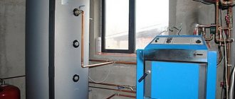
- It is better to connect the Leningradka solid fuel boiler through a three-way mixing valve and a buffer tank. Since there is too little coolant in the system, there is a risk of overheating and boiling. Gravity distribution, holding more than 200 liters of water, can be connected directly to the TT boiler.
Typical connection diagram for a double-circuit wall-mounted boiler with a Leningradka
Important clarification. When assembling a home heating network, polypropylene pipes PN 22-28, reinforced with fiberglass, aluminum foil or basalt fiber, are often used. There is no standard size of 16 mm in the range of STABI PPR pipes; the minimum outer diameter is 20 mm. Accordingly, radiator connections are made with a cross-section of 20 x 2.8 mm.
The recommendations listed will help you organize heating correctly if you use single-pipe wiring wisely. For an analysis of common mistakes and questions regarding the installation of the Leningradka, see the next video:
Open system configuration
Heating of the open type is carried out using the following components:
- boiler;
- expansion tank (atmospheric type);
- water pipes;
- heating radiators;
- return pipeline;
- circulation pump (if open-type water heating with a pump is used);
- primary fill valve;
- valve for draining water.
Let us consider in detail the features and characteristics of the main constituent elements.
Boiler
When using an open type heating device, the following types of boilers can be used:
- Units operating on gas fuel are used where a gas main can be laid to the house. This option is the most profitable due to the affordable price of energy resources. However, you will first have to make a project and coordinate it with the relevant services.
- Solid fuel boilers can be used in regions where it is easy to buy coal or prepare firewood. Modern devices are quite economical, have high efficiency and do not require constant monitoring.
- Electric boilers are used less frequently because they are less economical than other types.
- Combined multifunctional boilers are the optimal solution because they can operate in several modes using different energy sources.
Circulation pump
Although an open circuit can operate on natural circulation, if possible, it is better to install a pump. This will increase heating efficiency. Although the device consumes electricity, it provides significant savings on the main energy carrier that the boiler uses.
When choosing a suitable pump, take into account the diameter of the pipe where it will cut into, the performance of the unit and the liquid pressure. The choice of pump is made taking into account its technical characteristics for a specific heating system.
Expansion tank
You can make the tank yourself or buy a ready-made one. It is better to use stainless steel containers. The tank must have a removable or hinged lid to control the liquid level. A pipe is installed on top to drain excess water.
There are several options for installing an expansion tank:
- at the highest point;
- on the return;
- on the far riser;
- with a pump installed on the supply.
Heating radiators
You can use the following types of radiators:
- Cast iron radiators are ideal for open heating. Due to the high inertia of cast iron radiators, impressive savings on energy are achieved.
- Steel batteries are lightweight and inexpensive. If they have an anti-corrosion coating, they will last quite a long time. However, it is better not to use them in open circuits due to rapid cooling, which will lead to frequent operation of the boiler and significant energy consumption.
- Aluminum radiators are easy and quick to install and are durable. They have high heat transfer and good thermal capacity. However, aluminum is susceptible to oxygen corrosion, so choose devices with an anti-corrosion coating.
- Bimetallic radiators, although expensive, combine the advantages of all of the above batteries. They are suitable for high pressure heating systems. However, it is impractical to install them in private houses with an open circuit in which atmospheric pressure is maintained.
Pipes of an open heating system
To install a heating circuit, it is important to choose pipes from a suitable material, as well as determine their diameter. For an open heating device, you can choose the following options:
For an open heating device, you can choose the following options:
- steel and metal pipes are almost never used today because they are very heavy and difficult to install;
- copper pipelines are high-quality, reliable, but expensive;
- metal-plastic pipes are of quite high quality, but the reliability of fitting connections leaves much to be desired and requires constant monitoring of leaks;
- the best option is considered to be pipelines made of cross-linked polyethylene with reinforcement and protection against oxygen oxidation (they are very reliable and easy to install);
- the most inexpensive option is to use polypropylene pipes with fiberglass reinforcement (for installation you will need a welding machine, which can be rented).
Types of circulation pumps
A pump with a “wet” rotor is made of stainless steel, cast iron, bronze or aluminum. Inside there is a ceramic or steel motor
To understand how this device works, you need to know the differences between the two types of circulation pumping equipment. Although the fundamental design of a heating system based on a heat pump does not change, the two types of such units differ in their operating features:
- A pump with a “wet” rotor is made of stainless steel, cast iron, bronze or aluminum. Inside there is a ceramic or steel motor. The technopolymer impeller is mounted on the rotor shaft. When the impeller blades rotate, the water in the system is set in motion. This water simultaneously functions as an engine cooler and a lubricant for the working elements of the device. Since the “wet” device circuit does not provide for the use of a fan, the operation of the unit is almost silent. Such equipment only works in a horizontal position, otherwise the device will simply overheat and fail. The main advantages of a wet pump are that it does not require maintenance and also has excellent maintainability. However, the efficiency of the device is only 45%, which is a minor drawback. But for domestic use this unit is perfect.
- A pump with a “dry” rotor differs from its counterpart in that its motor does not come into contact with the liquid. As a result, the unit has less durability. If the device operates “dry,” then the risk of overheating and failure is low, but there is a risk of leakage due to abrasion of the seal. Since the efficiency of a dry circulation pump is 70%, it is advisable to use it to solve utility and industrial problems. To cool the engine, the device circuit provides for the use of a fan, which causes an increase in the noise level during operation, which is a disadvantage of this type of pump. Since in this unit water does not serve as a lubricant for working elements, during operation of the unit it is necessary to periodically carry out technical inspection and lubricate parts.
In turn, “dry” circulation units are divided into several types according to the type of installation and connection to the engine:
- Console. In these devices, the engine and housing have their own place. They are separated and firmly fixed on it. The drive and working shafts of such a pump are connected by a coupling. To install this type of device, you will need to build a foundation, and maintaining this unit is quite expensive.
- Monoblock pumps can be used for three years. The body and engine are located separately, but are combined by a monoblock. The wheel in such a device is installed on the rotor shaft.
- Vertical. The service life of these devices reaches up to five years. These are sealed advanced units with a seal on the end side made of two polished rings. For the manufacture of seals, graphite, ceramics, stainless steel, and aluminum are used. When the device is running, these rings rotate relative to each other.
There are also more powerful devices on sale that have two rotors. This dual circuit allows you to increase the performance of the device at maximum load. If one of the rotors fails, the second can take over its functions. This allows not only to enhance the operation of the unit, but also to save energy, because with a decrease in heat requirements, only one rotor works.
