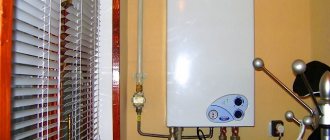
Currently, for every resident of an apartment building, the issue of saving costs on housing and communal services is of fundamental importance. They can be reduced not only by systematically recording the amount of resources consumed, but also by choosing a property with modern utilities. A special device allows you to reduce energy consumption and at the same time ensure optimal temperature conditions in the room in winter. Let's consider what an individual heating point (IHP) is as the best option for saving utilities.
Advantages and disadvantages of air heating
To make a choice, consider the features of using such systems in private homes:
Heating of a private house, the fireplace acts as a heating element.
Estimated service life is 30 years. Usually, after a couple of years, the costs of VO are fully repaid to the owners. No leaks or risk of pipe freezing, high efficiency, no intermediate transmission elements and low energy consumption. Fans can “cooperate” with a conventional stove and supply warm air to all rooms. A well-known example is fireplace air heating of a private house. Filters and ionizers can purify the air of odors and eliminate harmful particles. The system creates an optimal microclimate, producing additional air humidification or drying, depending on the characteristics of the climate and the room. In the summer, you can cool the room using air ducts with additional draft that supply cool air. If you are not at home, the system operates at a minimum and quickly increases the temperature when necessary. The main disadvantage is the need for power supply to the forced circulation system and the need for backup power if power outages are expected. Support for installing the system is laid only during the construction of a building or complex repairs are carried out with subsequent installation. VO is quite demanding in terms of repair and maintenance; with regular use, it is difficult to carry out a full modernization.
The procedure for installing a thermal energy metering unit
Work on installation, commissioning and startup of the system is carried out in the following order:
- Inspection of the premises and determination of the scope of work for a specific house;
- Development of project documentation with subsequent acceptance of the project;
- Installation work with equipment (insertion and electrical installation activities);
- Commissioning (programming and testing the network functionality);
- Conclusion of an agreement with subsequent registration on the balance sheet of the heat service company.
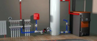
Parsing the circuit
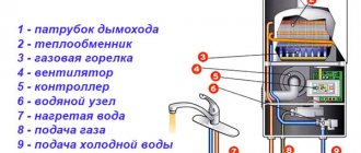
As you understand, the unit consists of filters, an elevator, instrumentation and fittings. If you plan to install this system yourself, then it’s worth understanding the diagram. A suitable example would be a high-rise building, in the basement of which there is always an elevator unit.
In the diagram, the system elements are marked with numbers:
1, 2 – these numbers indicate the supply and return pipelines that are installed in the heating plant.
3.4 – supply and return pipelines installed in the heating system of the building (in our case, this is a multi-storey building).
5 – elevator.
6 – this number indicates coarse filters, which are also known as mud filters.
7 – thermometers
8 – pressure gauges.
The standard composition of this heating system includes control devices, mud traps, elevators and valves. Depending on the design and purpose, additional elements may be added to the unit.
Interesting! Today, in multi-storey and apartment buildings you can find elevator units that are equipped with an electric drive. This modernization is needed in order to adjust the nozzle diameter. Due to the electric drive, the thermal fluid can be adjusted.
It is worth saying that utilities become more expensive every year, and this also applies to private homes. In this regard, system manufacturers provide them with devices aimed at saving energy. For example, now the circuit may contain flow and pressure regulators, circulation pumps, pipe protection and water purification elements, as well as automation aimed at maintaining a comfortable mode.
Also in modern systems a thermal energy metering unit can be installed. From the name you can understand that it is responsible for accounting for heat consumption in the house. If this device is missing, the savings will not be visible. Most owners of private houses and apartments strive to install meters for electricity and water, because they have to pay significantly less.
Possible problems
As a rule, most problems in the elevator unit arise for the following reasons:
- clogging in equipment;
- changes in the diameter of the nozzle as a result of equipment operation - an increase in the cross-section makes it more difficult to regulate the temperature;
- blockages in mud traps;
- failure of shut-off valves;
- regulator failures.
In most cases, finding out the cause of problems is quite simple, since they are immediately reflected in the temperature of the water in the circuit. If the temperature differences and deviations from the standards are insignificant, there is probably a gap or the nozzle cross-section has increased slightly.
A difference in temperature readings of more than 5 ℃ indicates the presence of a problem that can only be solved by specialists after diagnostics.
If, as a result of oxidation from constant contact with water or involuntary drilling, the cross-section of the nozzle increases, the balance of the entire system is disrupted. Such a flaw must be corrected as quickly as possible.
It is worth noting that in order to save money and use heating more efficiently, electricity meters can be installed at heating units. And hot water and heat meters make it possible to further reduce utility bills.
Types of air heating
In an air system, as in a water system, the coolant can be driven in two ways:
Due to convection (gravitational system)
Here, only the Archimedes force is used as an engine, forcing heated air, the density of which decreases, to float, that is, to move upward.
To do this, it is enough to place the heat generator below the lowest consumer - and that’s it, the air will follow where it needs to go on its own. This method has three disadvantages:
the power of the convective flow is not too great, so it will not be possible to install a filter; for the same reason, a slight draft can disrupt the supply of warm air.
The air has to be heated quite strongly, otherwise the Archimedean force will not be able to overcome the aerodynamic resistance of the air ducts.
Using a fan (forced supply)
This system is not afraid of drafts, and the heat generator can be placed in it at any level. In addition, the air can be heated only slightly, which is very convenient during the off-season. The cross-section of the air ducts can be reduced, since their aerodynamic resistance is no longer important.
For all these advantages you will have to pay both in the literal sense (the fan and the electricity driving it cost money) and in the figurative sense - the system becomes energy-dependent.
In addition, air heating can be direct-flow or recirculating.
Heat meter
The heat meter is the main element of which the thermal energy unit should consist. It is installed at the heat input into the heating system in close proximity to the balance sheet boundary of the heating network.
When installing a metering device remotely from this boundary, heating networks add losses in addition to the meter readings (to account for the heat that is released by the surface of pipelines in the area from the balance separation boundary to the heat meter).
The principle of operation of the node
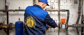
Understanding what an elevator is, it is worth noting the need for this complex to connect heating networks and private consumers with its help. The thermal unit is a module that performs the functions of pumping equipment. To see what an elevator is in a heating system, you need to go down into the basement of almost any apartment building. There, among the shut-off valves and pressure meters, you will be able to find the desired element of the heating system (the diagram is shown in the figure below).
When figuring out what an elevator is, it is worth determining its functionality based on the tasks it performs. These include the redistribution of pressure from inside the heating system, while dispensing coolant at an acceptable temperature. In fact, the volume of water doubles, moving along the lines from the boiler room. This effect is achieved in the presence of water in a separate sealed vessel.
The temperature of the coolant coming from the boiler room is usually in the range of 105-150 0 C. It is not possible to use it with this parameter in domestic conditions for safety reasons.
Regulatory documents regulate the limiting temperature value for the coolant, which should be no more than 95 0 C.
For reference. Currently, the issue of reducing the temperature of hot water from 60 0 C, provided for by SanPin, to 50 0 C, is being actively discussed, citing the need to save on resources. As experts note, the consumer will not notice such a minimal difference, and in order to ensure proper disinfection of water in pipes every day, it is recommended to increase it to 70 0 C. It is too early to judge how rational and thoughtful this initiative is. Changes to SanPin have not yet been made.
Returning to the topic of the heating system elevator, we note that it is he who provides the temperature in the system. Thanks to these actions, it is possible to reduce risks:
- With overheated batteries it is easy to get burned;
- Heating radiators are not always able to withstand long-term exposure to elevated coolant temperatures under pressure;
- The wiring of polymer or metal-plastic pipes does not provide for their use with such hot coolants.
Why is this particular node convenient?
Elevator unit in any apartment building
You can hear the opinion that it would be more convenient not to use a heating elevator with this operating principle, but to directly supply water at a lower temperature. However, this opinion is erroneous, because the diameters of the lines will have to be significantly increased to transfer the colder coolant.
In fact, a competent design of a thermal heating unit allows you to mix into the supply volume of water part of the return volume, which has already cooled down. Although some sources refer to the elevator unit of the heating system as outdated hydraulic equipment, it has proven its effectiveness in operation. More modern devices used instead of the elevator unit circuit are the following types:
- plate heat exchanger;
- mixer with three-way valve.
Elevator operation
Considering the elevator unit of the heating system, what it is and how it works, it is worth noting that the working design is similar to water pumps. However, operation does not require energy transfer from other systems. It shows its reliability under certain conditions.
From the outside, the base part of the device is similar in appearance to a hydraulic tee mounted on the return branch. However, through a standard tee, the coolant would painlessly penetrate into the return line without passing through the radiators. Such behavior would be meaningless.
Standard elevator layout
The classic diagram of the elevator unit of the heating system contains the following components:
- A prechamber, a supply pipe, at the end of which there is a nozzle of a certain diameter. The coolant enters it from the return.
- A diffuser is mounted in the outlet part. It transfers water to consumers.
Today there are units where the diameter of the nozzle is adjusted by an electric drive. This makes it possible to optimize the coolant temperature automatically.
The choice of a unit with an electric drive is based on the fact that it is possible to change the coolant mixing coefficient within 2-5, which is impossible in elevators where the nozzle diameter is not adjustable. Thus, a system with an adjustable nozzle allows significant savings on heating, which is possible in houses where central meters are installed.
How does a thermal unit circuit work?
In general, the operating principle can be described as follows:
- water moves along the line from the boiler room to the entrance to the nozzle;
- during passage along a small diameter, the speed of the working coolant increases significantly;
- an area with a slight vacuum is formed;
- due to the resulting vacuum, water is sucked from the return;
- turbulent flows in a homogeneous mass are sent to the outlet through the diffuser.
You can see everything in more detail on the working diagram.
For efficient operation of the system, which involves the circuit of the elevator unit of the heating system, it is necessary to ensure that the pressure between the supply and return is greater than the value of the calculated hydraulic resistance.
Disadvantages of the system
In addition to positive qualities, a thermal unit or thermal unit diagram has a certain drawback. They are as follows. The heating system elevator does not have the ability to adjust the output temperature mixture. In such a situation, you will need to measure the heated coolant from the main line or from the return pipeline. It will be possible to lower the temperature only by changing the dimensions of the nozzle, which is structurally impossible to do.
In some cases, elevators with electric drives save the day. Their design includes a mechanical drive. This unit is driven by an electric drive. In this way it is possible to vary the diameter of the nozzle. The basic element of this design is the throttle needle, which has a conical shape. It fits into the hole along the inner diameter of the structure. Moving over a certain distance, it manages to adjust the temperature of the mixture precisely by changing the diameter of the nozzle.
Both a manual drive in the form of a handle and a remote-started electric drive can be mounted on the shaft.
Possible problems
The heating system of a house is a complex mechanism. Some breakdowns and malfunctions are inevitable. But most often problems arise in the heating unit, namely, elevator failures. Reasons of a mechanical nature: defects in shut-off equipment, clogged filters. Because of this, a temperature difference occurs in the pipes before and after passing through the elevator. If the difference is not big, then the problem is not serious: you just need to clean the elevator. Otherwise, repairs are necessary.
Other problems with the heating unit include an increase in the permissible temperature of the measuring equipment and the occurrence of leaks in pipes. When the filters in the pipes become clogged, the pressure increases.
Important! In case of any problem, it is necessary to diagnose the entire heating system.
As already mentioned in the article, elevator units are an obsolete technology. Gradually, in apartment buildings they are being replaced by automatic heating units, which do not require constant human control and regulate all indicators themselves.
The disadvantage of such heating systems is their high cost and, like any automated device, it runs on electricity.
However, devices are built into the circuit of single-circuit units that make it possible to regulate the temperature and pressure in the incoming coolant. Thus, it allows people to save money when paying for utilities.
Heat exchanger based models
There is another type of heating unit for a private house - based on a heat exchanger.
In this case, a special heat exchanger is attached to the device, which separates the liquid from the heating main from the liquid in the room. This function is necessary for additional preparation of the coolant using various additives and filtering devices. The scheme expands the possibilities for regulating the pressure and temperature of the coolant inside the building. Thus, heating costs for the building are significantly reduced. Thermostatic valves must be used to mix water at different temperatures. Such systems interact normally with aluminum radiators, but in order for the latter to last as long as possible, it is necessary to carefully select the coolant, abandoning low-quality raw materials. Of course, keeping track of the quality of the liquid is problematic, so it is better to abandon this material, giving preference to bimetallic or cast iron radiators.
The DHW connection diagram involves the use of a heat exchanger. This method provides many advantages, including :
- 1. Possibility of adjusting water temperature.
- 2. Possibility of changing the pressure of the hot coolant.
Unfortunately, many management companies do not monitor the coolant temperature, and sometimes even lower it by several degrees. The average consumer will hardly notice such changes, but on the scale of an entire home, this means saving impressive amounts of money.
Types of heat meters depending on the measurement method
Currently, the following types of heat meters are widely used:
- Mechanical operating principle or tachometer. The most common modification of heat metering devices. There are vane or rotor (turbine) ones. Quite easy to use and does not require electrical costs. They work thanks to an impeller or rotor and reciprocating fluid movement;
Important! Mechanical heat meters are demanding of the coolant; the water must be clean. The device is equipped with an additional filter element, since its contamination directly affects the accuracy of the readings.
- Electromagnetic. The operating principle is based on interaction with electric waves of the coolant. Of all the presented categories, these metering devices are the most accurate. The disadvantage of the device is its use in horizontal thermal systems;
- Ultrasonic. Thermal energy is measured by measuring the length of the ultrasound signal passing through the coolant. The meters are installed in pairs, opposite each other. They also differ from each other according to: frequency, time, correlation and Doppler principles of operation. Used in open and closed thermal systems;
- Vortex type. They create a vortex flow in the liquid, due to their location on the path of coolant movement, with subsequent recording of the formation and disappearance of magnetic field vortices. It is used in vertical and horizontal heating systems.
Important! Vortex heat meters require straight pipelines, since the quality of measurements directly depends on the composition of the moving hot liquid, its speed and the presence of air masses in it.
Three way valve
If it is necessary to divide the coolant flow between two consumers, a three-way heating valve is used, which can operate in two modes:
- constant mode;
- variable hydraulic mode.
A three-way valve is installed in those places in the heating circuit where it may be necessary to divide or completely shut off the flow of water.
The tap material is steel, cast iron or brass. Inside the faucet there is a shut-off device, which can be ball, cylindrical or conical. The tap resembles a tee and, depending on the connection, a three-way valve on a heating system can work as a mixer. Mixing proportions can be varied within wide limits. The ball valve is mainly used for:
- adjusting the temperature of heated floors;
- adjusting battery temperature;
- distribution of coolant in two directions.
There are two types of three-way valves - shut-off and control valves. In principle, they are almost equivalent, but with three-way shut-off valves it is more difficult to regulate the temperature smoothly.
Tips and tricks for installing UUTE
The main recommendation when installing heat metering units is the requirements for the human factor.
The estimate for the entire project for a specific structure, as well as further installation of equipment, must be made by specialists with specific knowledge and skills in this field. In this case, common property will last much longer.
Sources
- https://kaminguru.com/sistema-otoplenija/uzel-uchjota-teplovoj-jenergii.html
- https://FB.ru/article/220674/teplovoy-uzel-uzel-ucheta-teplovoy-energii-shemyi-teplovyih-uzlov
- https://4schetchika.ru/otoplenie/uzel-ucheta-teplovoy-energii-ustanovka-uute-shemy/
- https://www.tproekt.com/chto-takoe-uzel-ucheta-teplovoy-energii/
- https://ests.msk.ru/teplosnabzheniye/uzly-ucheta/montaj-i-ustanovka
- https://nedexpert.ru/vse-o-nedvizhimosti/ustanovka-uutje-v-kvitancii-chto-jeto-takoe/
[collapse]
Thermal sensor
This device is mounted on the return pipeline together with shut-off valves and a flow meter. This arrangement allows not only to measure the temperature of the circulating fluid, but also its flow rate at the inlet and outlet.
Flow meters and temperature sensors are connected to heat meters, which allow calculation of consumed heat, storage and archiving of data, registration of parameters, as well as their visual display.
As a rule, the heat meter is located in a separate cabinet with free access. In addition, additional elements can be installed in the cabinet: an uninterruptible power supply or a modem. Additional devices allow you to process and control data that is transmitted by the metering unit remotely.
Installation and installation of energy metering units - procedure
Installation of metering units at sites involves two areas of work: cutting thermomechanical parts into pipes and carrying out electrical installation work.
The result of all actions is the connection of sensors and flow meters to the computer. After this, the computing unit is launched. The next step is to debug all connected modules. It is carried out using software configuration of the computer and subsequent testing of the system. The unit is handed over after successful completion of the inspection.
Procedure for installing metering units:
- Drawing up design and estimate documentation for a heat metering unit
- Coordination of the project with the supplier company
- Design of the device configuration
- Production of unit modules according to existing drawings
- Insertion of modular blocks into existing networks
- Electrical installation and debugging work
- Delivery of the finished project to the customer
Permission to operate
When a heating unit is admitted for operation, the compliance of the serial number of the metering device, which is indicated in its passport, and the measurement range of the established parameters of the heat meter with the range of measured readings, as well as the presence of seals and the quality of installation, are checked.
Operation of the heating unit is prohibited in the following situations:
- The presence of tie-ins in pipelines that are not provided for in the design documentation.
- The operation of the meter is outside the accuracy standards.
- Presence of mechanical damage to the device and its elements.
- Broken seals on the device.
- Unauthorized interference with the operation of a heating unit.
Installation procedure
Before installing the heating unit, a number of preparatory actions must be carried out:
- a positive decision made at a general meeting of owners (tenants of the house);
- contacting a resource supplying organization with an order for the preparation of technical specifications by specialists, and receiving it;
- initiation of a design survey (to determine the condition and list of previously installed units);
- creation (in a specialized company with a license) and approval of the corresponding project;
- conclusion of a contract.
Only after these steps can you begin to install the modular installation and carry out commissioning of the ITP. They should be handled by an organization that has experience and the right to carry out such work.
Classification of heat supply systems according to the method of organizing heating systems
According to the method of organizing heating systems in apartment buildings, heat supply systems are divided into:
· Dependent;
· Independent.
Dependent heat supply systems are systems in which water is heated and supplied to the heating and hot water system directly, that is, in heating radiators and in taps - the same.
Independent heat supply systems are systems in which the coolant in the heating networks transfers heat to the internal heating system of an apartment building through a plate heat exchanger.
Composition and location
Apartment buildings can have different configurations. Because of this, the UUTs may be different in appearance and design from each other.
Such units can also be installed for a private house if it is connected to a central heating system
However, the main elements are included in each node:
- Shut-off and control valves. Devices and devices for regulating and completely shutting down various components of the heating system.
- Heat meter. The main measuring device, which may differ in design, but is required to give readings of the main parameters of heat supply.
- Sump. Garbage collection site. The main purpose of this device is to prevent foreign objects and substances from entering the heating system.
- Flow meter. A device that takes into account coolant flow and helps regulate its supply.
- Elevator. The elevator heating unit serves to regulate the temperature of the coolant. In this device, by mixing hot and cooled coolant (return), adjustment occurs to standard values.
- Thermal sensor. A measuring device for recording the temperature of the coolant when returning from the heating system.
- Auxiliary equipment. Many control centers are provided with additional devices and units. Modern technologies can significantly expand control capabilities.
The main requirement for the arrangement of instruments and all components of the control system is maximum accuracy and efficiency. Therefore, there are certain rules for the sequence and location of the main nodes. Here are just a few of them:
- Place metering devices at the interface, as close as possible to valves and coolant supply regulators.
- Prohibition on the installation of additional pipeline outlets that bypass sensors.
- The temperature sensor on the return line is placed in front of the valve on the outside.
- Place instruments so that there is good visual access for taking instrument readings and servicing them.
This is interesting: the principle of a two-way valve for heating.
Following the basic instructions, it will not be difficult to equip a heating metering unit if you have all the necessary components for its operation.
The layout and sequence are thought out in advance, making the necessary drawings and calculations.
Rules and regulations applied in heat supply systems of MKD
The organization of the heat supply system of an apartment building is strictly regulated by legislative acts and SanPiN norms.
So, according to SanPiN 2.1.4.2496-09:
“The temperature of hot water at water points, regardless of the heat supply system used, must be no lower than 60 °C and no higher than 75 °C.”
The temperature of hot water must be more than 60 degrees Celsius to disinfect it from viruses and bacteria, which can survive at lower temperatures, but die at values above this figure.
On the other hand, using water heated above 75 degrees is unacceptable, as it can lead to burns.
According to the Decree of the Government of the Russian Federation of May 6, 2011 N 354 “On the provision of utility services to owners and users of premises in apartment buildings and residential buildings”:
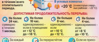
1. The heating system must provide the standard air temperature:
a. in residential premises - not lower than +18 °C (in corner rooms +20 °C);
b. in areas with the coldest five-day temperature -31 °C and below +20 °C (in corner rooms from +22 °C);
c. in other premises, in accordance with the requirements of the legislation of the Russian Federation on technical regulation.
2. The heating system must ensure an acceptable excess of the standard temperature of no more than 4 °C;
3. The permissible decrease in standard temperature at night (from 0.00 to 5.00 hours) is no more than 3°C;
4. Reducing the air temperature in a living room during the daytime (from 5.00 to 0.00 hours) is not allowed.
Installation of UUTE: important aspects
Any interference in the functioning of the heating unit is authorized by the heat supply organization. Carrying out installation work at a heating station by a person who does not have access and is not certified in the prescribed manner is fraught with failure of the entire system.
Installation of a heat metering unit must be carried out in compliance with safety regulations, fire safety and sanitary standards only by specially trained technical personnel.
The cost of implementing a standard 2-channel heat metering unit for a diameter of 50
The cost of a thermal energy metering unit depends on a large number of parameters: the diameters of the pipes through which the coolant is supplied to the facility, the number and type of inputs, the required number of metering points, the channels of the meters, the possibility of remote reading of indicators and other characteristics of the facility.
| Scope of work for the implementation of UUTE based on different manufacturers: | DN 50 VIS.TS |
| Development of the UUTE project with approval | 45 000 as part of a work package |
| Supply of equipment and materials: Computing unit Set of flow meters, thermocouples, sensors Associated materials, pipes, fittings, valves | 160 000 |
| Construction and installation works | 88 000 |
| Delivery and execution of commissioning certificates | 27 000 |
| TOTAL: | 320 00 |
Duration of work: from 35 working days Stage 1. Request for technical specifications from the heat supply organization, development and approval of a design for a heat metering unit - 14 working days; Stage 2. Purchase and delivery of equipment and materials – 10 working days; Stage 3. Construction and installation work – 5 working days; Stage 4. Delivery of UUTE into operation by the heat supply organization - 6 working days; Stage 5. Warranty for work and equipment for 12 months.
To clarify the price for your facility, call +7 (495) 777-22-10 our specialist in heat metering units and he will clarify all the necessary details to select equipment and calculate the cost of all work. You can also send an application using the online form or by email and we will contact you. An engineer’s visit for an initial inspection of the facility is free.
When developing the project, the following regulatory and technical documentation is used:
- Rules for commercial accounting of thermal energy and coolant, approved by Decree of the Government of the Russian Federation of November 18, 2013 No. 1034 (hereinafter referred to as the Accounting Rules);
- Rules for the design and safe operation of steam and hot water pipelines (PB 10-573-03) approved. Resolution of the Gosgortekhnadzor of the Russian Federation dated June 11, 2003 No. 90;
- Safety regulations for the operation of thermal mechanical equipment of power plants and heating networks, approved. Ministry of Fuel and Energy of the Russian Federation April 3, 1997;
- Rules for electrical installations;
- Rules for the technical operation of thermal power plants, approved by order of the Ministry of Energy of the Russian Federation dated March 24, 2003 No. 115;
- “Recommendations for the selection, installation and operation of metering devices for thermal energy consumption, cold and hot water for energy and resource conservation in the housing and communal services sector,” prepared by the Academy of Public Utilities named after. K.D. Pamfilova;
- Handbook for setting up and operating water heating networks. IN AND. Manyuk et al., Moscow, 1988;
- “Methodology for determining the maximum and minimum flow rates of coolant and water at heating points when choosing heat and water meters,” M.A. Lapir, Department of Fuel and Energy Economy of the Moscow Government, 10/27/1998;
- SP 41-101-95 “Design of heating points”;
- SP 60.13330.2012 “Heating, ventilation and air conditioning”;
- SP 124.13330.2012 “Heating networks”;
- SNiP 3.05.06-85 “Electrical devices”;
- SNiP 3.05.07-85 “Automation systems”;
- SNiP 21-01-97 “Fire safety of buildings and structures”;
- GOST 2.701-2008 “Unified system of design documentation. Scheme. Types and types. General requirements for implementation";
- GOST 21.110-2013 “System of design documentation for construction. Specification of equipment, products and materials";
- GOST R21.1101-2013 “System of design documentation for construction. Basic requirements for design and working documentation";
- GOST 21.208-2013 “Automation of technological processes. Symbols of devices and automation equipment in diagrams";
- GOST 21.408-2013 “System of design documentation for construction. Rules for the implementation of working documentation for automation of technological processes";
- GOST 21.602-2003 “System of design documentation for construction. Rules for the implementation of working documentation for heating, ventilation and air conditioning";
Repair and maintenance of heating systems
Depending on the source of heat supply, repair and maintenance of heat supply systems in an apartment building is carried out differently.
With a centralized heat supply system, maintenance is carried out annually, which includes the following activities:
· Hydraulic testing of thermal units, heating networks, heating systems, hot water supply systems;
· Flushing the heating system;
· Inspection of heat consumption systems equipment;
· Diagnostics, repair and maintenance of thermal energy metering unit;
· Current repairs of heat consumption systems;
· Washing of heat exchange equipment.
With a local decentralized heat supply system:
· Maintenance of boiler equipment;
· Hydraulic testing of thermal units, heating systems, hot water supply systems;
· Annual flushing of the heating system;
· Inspection of heat consumption systems equipment (checking pressure gauges, thermometers, packing gland seals on valves);
· Routine repair of heat consumption systems (in accordance with defect reports);
· Washing of heat exchange equipment;
· Inspection and audit of heat exchange equipment, pumping equipment;
· Pressure pumping in the expansion tank;
· Maintenance and repair of gas equipment.
With an individual decentralized heat supply system, a set of works is carried out necessary to maintain the heat supply system equipment in operational condition:
· Checking the heating and hot water system for tightness;
· Checking safety valves;
· Cleaning filters;
· Pressure pumping in the expansion tank;
· Monitoring of pumping equipment.
Mandatory measures in this case also include maintenance of gas equipment.
How does the process of heating a high-rise building take place?
Each apartment building has a central heating system, which consists of the following elements:
- source;
- heating network;
- consumer.
Boiler houses and thermal power plants act as sources of thermal energy.
From boiler rooms to houses, hot water is sent immediately and requires a decrease in temperature, otherwise the heating equipment of the house will be damaged. In a thermal power plant, it is converted into steam to produce electricity, then this steam is used to heat the coolant entering the heating network of the building.