Start-up of the boiler plant
3.2.1.
Before lighting the boiler, it is necessary to carry out a pre-start check of the closure of the shut-off valves on the oil pipelines in front of the burners and ignition devices in accordance with the operating instructions. 3.2.2. Before starting up the boiler after an outage of more than 3 days, the serviceability and readiness to turn on the draft mechanisms of the boiler, its auxiliary equipment, measuring instruments and remote control of fittings and mechanisms, auto regulators must be checked, and the operability of protections, interlocks, operational communication equipment must be checked. triggering of the slam-shut valve. When downtime is less than 3 days, equipment, mechanisms, protection devices, interlocks, and measuring instruments on which repairs were carried out are subject to inspection. Identified malfunctions must be eliminated before starting the boiler.
3.2.3. Before starting the boiler, it is necessary to ensure the pressure of fuel oil and steam, air and draft in accordance with the requirements of the operating instructions.
The temperature of the fuel oil before mechanical and steam-mechanical nozzles must correspond to its viscosity of no more than 2.5 °VU, and before steam and rotary nozzles - no more than 6 °VU.
3.2.4. Immediately before igniting the burners, the firebox and gas ducts (including recirculation) must be ventilated for at least 10 minutes with the gas-air duct dampers open and the air flow rate at least 25% of the nominal. The conditions that ensure the required air flow for ventilation must be specified in local regulations. At the same time, the “warm box” must be ventilated.
3.2.5. Ventilation of boilers operating under pressurization, as well as hot water boilers in the absence of smoke exhausters, should be carried out by blower fans and gas recirculation smoke exhausters.
3.2.6. The firing of boilers with balanced draft should be carried out with the smoke exhausters and blower fans turned on, and the kindling of boilers operating under pressurization should be carried out with the blower fans turned on.
3.2.7. The firing of a sulfur fuel oil boiler must be carried out with the air heating system in front of the air heater previously turned on.
3.2.8. According to explosion safety conditions, the firing of a fuel oil boiler can begin with the ignition of any burner or group of burners and be carried out in the sequence specified in the boiler installation operating instructions.
3.2.9. If any of the burners goes out or does not ignite when ignited, the supply of fuel oil to it must be immediately stopped and the ignition device must be turned off. Ignition of the boiler can continue by igniting subsequent burners if at least one burner remains in operation. If there is not a single burner left in operation, then you should be guided by the instructions in paragraph. The switched-off burner must be re-ignited after eliminating the reasons for its extinguishing or non-ignition.
3.2.10. When lighting the boiler, the burners must be ignited using an ignition device; The ignition device must be switched off after stabilization of the burner flame.
(New edition. Change No. 2)
3.2.11. In the event of a torch break in the furnace, the fuel supply to the boiler must be immediately stopped and the pilot lights must be turned off. Only after ventilating the firebox and flues for 10 minutes and eliminating the reasons for the firebox going out can you begin to kindle.
Popular makes and models
Fuel oil boilers are produced by many domestic and foreign companies.
The following brands received the highest ratings from users:
- "KV Boiler". The Russian manufacturer offers installations for industrial boiler houses with a capacity of up to 3 MW. The smallest unit costs 1.2 million rubles and is designed for a heated area of 25 thousand square meters. m.
- Buderus. German company, a world leader in the production of heating equipment. It offers several liquid fuel models, among them the G125 SE-25 at 25 kW for 136 thousand rubles. and G125 SE-32 at 32 (kW) for 151 (thousand rubles)
- Protherm. A manufacturer from Slovakia has combined oil heaters into the “Bison” series. Their cost is 36–55 thousand rubles. The burner is not included in the price; it must be purchased separately.
- De Dietrich Thermique. The product range of this company from France includes the GT line of liquid fuel units. All are made of high-quality corrosion-resistant cast iron. Their cost is 70–90 thousand rubles, the burner must be purchased additionally (for 35–38 thousand rubles).
- Unical. The Italian brand actively cooperates with leaders in the production of burner devices - companies FBR (Italy) and SAACKE (Germany). Produces various diesel and fuel oil boilers, incl. Trypass 12/15 series with reduced emission of substances harmful to the environment. Minimum power – 64 kW, cost – from 200 to 360 thousand rubles.
"Kotel KV" is a Russian manufacturer of fuel oil boilers.
SAACKE burners operate efficiently even with dirty fuel and do not require frequent cleaning.
Advantages of liquid fuel boilers
- There are quite obvious advantages of liquid fuel boilers used in industries related to fuels and lubricants. For private homes, the advantages of boilers of this type may raise questions:
- Liquid fuel boilers have a high efficiency of 86 to 98%. This is a good indicator, and it is very close to the indicators of gas boilers;
- An undoubted advantage of diesel boilers, unlike gas boilers, is that you do not need permits (approvals) to install the boiler. Although the combustion room will still have to be equipped;
- Diesel boilers are produced in the most autonomous configurations. Automation of boilers and automatic fuel supply allow minimizing the presence of a person for maintenance;
- Another plus is the ability to quickly and easily, by changing the boiler burner, switch to working with natural gas;
- Although there are no omnivorous boilers, diesel boilers can operate on alternative types of liquid fuel, as indicated in the documentation for the boiler;
- Liquid fuel boilers can fit into any heating system and can work with any coolant (water and antifreeze).
Advantages and disadvantages
The strengths of oil-fired boilers are:
- High degree of automation.
- Work with minimal human intervention.
- Regulation of heat transfer over a wide range.
- Widespread availability of fuel.
- Versatility. Most models can be easily and inexpensively converted to use gas.
- Easy installation. There is no need to obtain permission or order a project.
- There are no requirements for the height and diameter of the chimney. The pipe can be laid horizontally and brought outside through the wall.
- Functional automation.
There are also disadvantages:
- High costs of heating a home.
- The need to frequently clean the burner device.
- Noise.
- Unpleasant smell.
- Dependence on electricity supply.
- Relatively low reliability due to the complex design, which includes the fuel supply system.
Oil farming
The oil farm consists of an open oil warehouse and a hardware room. An oil warehouse usually has above-ground metal tanks mounted on foundations of individual reinforced concrete posts. The open oil warehouse is fenced off from the rest of the territory by an earthen rampart 1.2 m high with a continuous sod. To drain surface water and drain oil in the event of a tank failure, the surface of the warehouse has a slope towards the sewer wells, from which it is planned to release water or oil beyond the TPP site. The oil facility must have four turbine oil tanks and four insulating oil tanks. The capacity of each tank is no less than the capacity of a railway tank - 70 m3, in addition, the permissible minimum capacity depends on the capacity of the oil system of the turbine unit and transformer. For emergency drainage of turbine oil, a special tank is provided at the power plant.
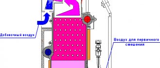
Rice. 9.6. Scheme of a vortex furnace with intersecting jets: 1 - cold radiation surface; 2 - firebox surface covered with refractory coating; 3 - fuel supply
Receiving and draining device
A railway unloading platform for receiving railway tanks with fuel oil is constructed in the form of two longitudinal walls, between which a drain tray is installed. The walls are made of concrete blocks. Depending on the height of the overpass wall and the load-carrying capacity of the tanks, reinforced concrete belts are made along the bottom and top of the walls.
When supplying fuel oil in tanks with a lifting capacity of 50-60 tons, the trestle with a drain tray can be made of a lightweight design without installing a reinforced concrete bottom. A more advanced overpass has also been developed with a drain tray made of reinforced concrete I-beam elements 5.6 m long, weighing 12.5 tons each, representing the walls of the overpass (Fig. 5.16). The lower bars of the walls are connected by loop joints, which are monolid and form the bottom. The walls along the top in the longitudinal direction are connected by loop joints. To avoid freezing of the base, slag filling is carried out under the bottom of the tray. The fuel oil drain tray has a longitudinal slope of 0.01 towards the center of the overpass, from where the fuel oil is drained into an intermediate container. Outlet trays are made of structures similar to those of a railway overpass.
The receiving capacity of the main fuel oil facility must be designed for at least 15% of the capacity of tanks installed for unloading. Typically, the receiving tank consists of two underground tanks with a capacity of 600-1000 m 3 each. To service the tanks, a special overpass is constructed from prefabricated reinforced concrete elements.
Types of regulation of oil burners
Burners installed for oil-fired boilers differ in the number of stages and the method of power adjustment. The main types of burners are:
- Single-stage - operation occurs at one power, which is pre-adjusted taking into account the permissible range.
- Two-stage - during operation it is possible to use both 100% and 50% power. The choice of operating mode and the transition to it is carried out by the automation system, while it is possible to configure modes with other indicators in the burner power range.
- Smooth two-stage - they have two operating modes at different powers, but the transition occurs smoothly.
- Three-stage - work is carried out in three operating modes.
- Modulating - the burner power is adjusted smoothly depending on the temperature or pressure in the boiler, heat generator or furnace.
Boiler plant
2.3.1. The design of the boiler furnace and the placement of burners in it must ensure the possibility of maintaining a stable combustion process and monitoring this process and exclude the possibility of the formation of stagnant and poorly ventilated zones.
2.3.2. The introduction of recirculating gases into the combustion chamber should not disrupt the stability of the combustion process.
2.3.3. For newly designed boiler plants with a steam capacity of at least 60 t/h, equipped with explosion safety valves, the frames and metal structures of the firebox and gas ducts must be designed for pressure inside the firebox and gas ducts exceeding atmospheric pressure by at least 200 kgf/m2 (2000 Pa). The frames of the firebox and flue ducts of newly designed boilers with a steam capacity of 60 t/h and above, the equipment of which with explosion safety valves is optional, must be designed for internal pressure exceeding atmospheric pressure by at least 300 kgf/m2 (3000 Pa), for installations operating under vacuum, and internal pressure exceeding the maximum operating pressure by at least 300 kgf/m2 (3000 Pa), for units operating under pressurization.
2.3.4. Lookouts must be installed in the boiler firebox to allow observation of combustion and eliminate the possibility of flame emission. The doors of manholes, hatches and peepholes in the furnace and gas ducts of the boiler must be tight and have strong locks that prevent their spontaneous opening.
2.3.5. Gas ducts on the combustion products exhaust line and gas ducts for recirculating combustion products into the boiler furnace must not have unventilated areas in which flammable gas could linger or accumulate.
2.3.6. The boiler air path from the air heater to the burners must be designed in such a way that it can be completely ventilated by blowing into the firebox.
2.3.7. On boilers, the volume where the collectors and boiler hangers are located (“warm box”) must be ventilated.
2.3.8. The areas for servicing fuel oil nozzles, as well as above the exhaust openings of the explosion safety valves of the furnace and gas ducts must be solid.
2.3.9. At boiler plants with a steam capacity of less than 60 t/h, except for boilers made of membrane gas-tight panels and boilers with single-pass gas movement, explosion safety valves are installed in cases provided for by the current “Rules for the design and safe operation of steam and hot water boilers.”
In boiler installations with a steam capacity of 60 t/h and above, explosion safety valves in the furnace and throughout the air and gas ducts up to the chimney may not be installed unless this is provided for in the boiler design.
Gas ducts from the boiler to the chimney must be designed for operating pressure (vacuum).
2.3.10. Boilers must be equipped with means for cleaning convective heating surfaces and air heaters.
2.3.11. Air heaters of boilers must be equipped with fire extinguishing means. Water should be used as the main fire fighting agent. To extinguish a fire in the convection shaft of a boiler with a tubular air heater, it is allowed to use superheated or dry saturated steam instead of water.
2.3.12. The pilot burners of operating boilers must be equipped with ignition protection devices. The remaining burners of operating boilers must be equipped with ignition (IPD) or ignition-protective devices (IPD).
All burners of newly commissioned boilers must be equipped with an emergency protection system.
2.3.13. A looker should be installed on each burner, allowing you to observe the torch of a given burner and the condition of the nozzle.
2.3.14. It must be possible to turn off the fuel supply to the burner manually from the maintenance platform.
2.3.15. The attachment of the nozzle to the block must ensure a tight connection and quick removal and installation of the nozzle. The use of a gasket in the connection between the injector and the block is not recommended.
Boiler manufacturing documentation
The boiler elements (boiler assembly) are manufactured in accordance with the requirements of the Technical Regulations of the Customs Union “On the safety of equipment operating under excess pressure” (TR CU 032/2013), relevant standards, technical documentation and technical specifications for the manufacture of TU 3112-001-92136322-2011 . GOST 8734-75, 8733-74 Cold-deformed seamless steel pipes GOST 8732-78, 8731-74 Hot-deformed seamless steel pipes. Boiler tubular elements are subjected to measurement control for deviations from size and shape and for permeability.
Boiler elements (boiler assembly) are tested with a test pressure of 20 kgf/cm2.
Normal operation of the boiler system
3.3.1. During boiler operation, it is necessary to monitor:
maintaining the combustion regime in accordance with the regime map, preventing the operation of the furnace with chemical incomplete combustion of fuel and the removal of soot particles from the furnace;
fuel oil pressure after the control valve, not allowing it to decrease below the limit specified in the regime map;
the temperature of the fuel oil in front of the nozzles, not allowing it to decrease below the values determined in accordance with the instructions in paragraph;
a torch, especially when switching from one type of fuel to another, preventing it from going out.
3.3.2. Cleaning the heating surfaces of an operating boiler must be carried out in accordance with the requirements of the operating instructions.
3.3.3. Inspection of fuel oil pipelines in a boiler room must be carried out regularly according to an approved schedule. The inspection periods are established in accordance with the “Rules for the technical operation of electrical stations and networks.”
3.3.4. At least once a shift, an external inspection of operating injectors should be carried out, and if necessary, they should be replaced.
Before installation on the boiler, oil nozzles must be tested on a water stand to check their performance and atomization quality.
At the power plant (boiler house), there must be a person responsible for the stand and testing of fuel oil nozzles on it.
3.3.5. While walking around a working boiler, it is prohibited to open hatches or manholes on the boiler, with the exception of briefly opening inspection hatches and peepholes when standing to the side of them.
Safe Operation
Liquid fuel boilers are considered high-risk objects. Improper operation of such units not only leads to a violation of thermal conditions, but can cause a boiler explosion or create a fire. Persons over 18 years of age who are certified to know the rules of safe operation are allowed to operate industrial liquid fuel units.
In domestic furnaces installed in residential buildings, the owner of such housing construction bears responsibility for safe operation. Therefore, he is obliged to follow all factory instructions for operating the installed boiler. This applies to the procedures for turning on, turning off, setting the operating mode and operating the fuel facility.
The manufacturer specifies the frequency and types of maintenance work for the unit. It is usually carried out annually before the unit is put into operation. This includes cleaning the external and internal surfaces of the boiler and smoke ventilation systems. Checking the condition of convective heating surfaces, pipelines, shut-off and control valves and primary sensors of the safety system.
Dead-end circuit
It is used when burning relatively low-viscosity fuel oils, when the boiler room operates at stable loads that exceed the average (Fig. 9.3). Fuel for pumps 3
comes from supply tank
5.
When installing a supply tank in the boiler room, it must be closed, with a volume of no more than 5 m3. It is not permitted to install a supply tank above boilers and economizers. The circuit must provide for the circulation of fuel oil from the pressure fuel oil pipeline of the pumps to the supply tank.
When the boilers are operating, the valves on the fuel oil lines behind the boiler burners are closed. When the boilers are stopped, these valves open and the recirculation line to the supply tank comes into operation. Fuel oil in the supply tank comes from the main tanks of the fuel oil storage facility.
Rice. 9.3. Dead-end liquid fuel supply circuit.
1
— fine filter;
2
and
6
—car heaters;
3
- pump;
4
and
9
- coarse filters;
5 — consumable container; 7 and 11 - fuel oil meters; 8 - circulation section; 10
— fuel supply from the main tank.
Fuel consumption is determined by a fuel oil meter 11,
Both rotational meters and special restriction devices can be used as fuel oil meters. Accounting for fuel consumption in a dead-end scheme is simpler than in a circulation scheme: accounting is carried out using one fuel oil meter in front of the boilers.
How to store diesel fuel
Fuel tank
Perhaps this is the very first question that faces the owners of a diesel boiler. And it’s true: there are special requirements for storing liquid fuels to ensure your safety.
There are 2 types of tanks for storing diesel fuel:
- open mounting - are plastic barrels made of polyethylene or PVC. Their kit must include a system for collecting fuel from the tank, a sealed lid and a float for determining the liquid level in the tank.
When can they be used? For storing fuel in small country houses, if the planned volume of diesel fuel does not exceed 1000 liters.
Large fuel storage tank
- closed installation - most often made of galvanized iron, however, recently it has also been possible to use chemically resistant plastic. They are installed in a pre-dug pit, which must be located at a distance of at least 5 meters from the foundation of the house. In this case, the system must be equipped with a pump to supply fuel from depth.
When can they be used? They are indispensable if you are going to store a large amount of diesel fuel (up to 20,000 liters).
Such systems must be equipped not only with level sensors, but also with fuel leakage sensors. Diesel fuel for filling the barrel is delivered by a special service for the sale of fuels and lubricants.
Topic 11. Liquid fuel burners
Oil nozzles (mechanical, with a spraying medium, combined steam-mechanical, rotary): design, principle of operation, scope, advantages and disadvantages. Air guide devices.
Oil nozzles.
The nozzle is one of three devices (along with the air guide device and the tuyere - embrasure) that form the burner.
Thermal power plants are supplied with gas from gas distribution stations (GDS) through gas distribution points (GRP) (Fig. 5.1.) The latter, together with the gas pipeline system, make up the gas supply of thermal power plants. At gas-oil condensing power plants with a capacity of up to 1200 MW and gas-oil thermal power plants with a steam flow rate of up to 4000 t/h, there can be one hydraulic fracturing unit, and at other power plants their number must be at least two. The performance of hydraulic fracturing at power plants where gas is the main fuel is calculated based on the maximum gas consumption of all working boilers, and at power plants that burn gas seasonally, based on gas consumption for the summer mode, hydraulic fracturing is located in separate buildings or under sheds on the territory of the power plant. Gas is supplied to each hydraulic fracturing unit via one gas pipeline (without a backup one) from a GDS power station located outside the territory. Gas pressure before the hydraulic fracturing is 0.6-1.1 MPa, and after the hydraulic fracturing its required value is determined by the pressure loss to the boiler furthest from the hydraulic fracturing and the required gas pressure in front of the burners and is usually 0.13–0.2 MPa.
Rice. 5.1.
I—
shut-off valve, 2—flow meter, 3—filter, 4—pressure regulator, 5—safety valve, 6—bypass line, 7—gas flow regulator; 8—pulse shut-off valve, 9—plug valve.
The hydraulic fracturing system has working gas pipeline lines, low-flow lines that are switched on when gas consumption is low, and a reserve line with manual control of the valves. On working lines and low-flow lines, automatic pressure regulators and protective regulators are installed, operating on the “after themselves” principle. Protective regulators are adjusted to higher pressure compared to the operating pressure and are completely open when operating within the design range.
Within the gas distribution zone and up to the boilers, gas pipelines are laid above ground. The gas supply from each gas distribution unit to the boiler room main and from it to the boilers is not reserved and can be carried out as a single line. The gas distribution manifold of the boilers is laid outside the boiler room building.
When filled with gas, gas pipelines must be blown through the discharge candles until all the air is displaced, and when emptying the gas, they must be blown through with air until all the gas is displaced. These requirements are due to the fact that when the volumetric concentration of natural gas in the air is 0.05-0.15 (5-15%), an explosive mixture is formed. From the waste candles, the gas is released to places from where it cannot enter buildings and where the possibility of its ignition is excluded from any source of fire. Only steel fittings are installed on gas pipelines.
Manufacturers of liquid fuel boilers
Power: 0 - 13 kW, heated area: up to 130.0 m2, voltage: 220 V, combustion chamber: closed, number of circuits: double-circuit (heating and hot water), heat exchanger: separate (stainless steel/stainless steel) , overall dimensions (HxWxD): 754x320x520
Power: 0 - 16.8 kW, heated area: up to 130.0 m2, voltage: 220 V, combustion chamber: closed, number of circuits: dual-circuit (heating and hot water), heat exchanger: separate (stainless steel/stainless steel) , overall dimensions (HxWxD): 700x325x602
Power: 0 - 17 kW, heated area: up to 170.0 m2, voltage: 220 V, combustion chamber: closed, number of circuits: double-circuit (heating and hot water), heat exchanger: separate (stainless steel/stainless steel) , overall dimensions (HxWxD): 754x320x520
Power: 0 - 21 kW, heated area: up to 210.0 m2, voltage: 220 V, combustion chamber: closed, number of circuits: double-circuit (heating and hot water), heat exchanger: separate (stainless steel/stainless steel) , overall dimensions (HxWxD): 754x320x520
Power: 15 - 15 kW, heated area: up to 150.0 m2, voltage: 220 V, combustion chamber: closed, number of circuits: double-circuit (heating and hot water), heat exchanger: separate (stainless steel/stainless steel) , overall dimensions (HxWxD): 930x365x650
Power: 13 - 13 kW, heated area: up to 130.0 m2, voltage: 220 V, combustion chamber: closed, number of circuits: double-circuit (heating and hot water), heat exchanger: separate (stainless steel/stainless steel) , overall dimensions (HxWxD): 781x370x683
Power: 17 - 17 kW, heated area: up to 170.0 m2, voltage: 220 V, combustion chamber: closed, number of circuits: double-circuit (heating and hot water), heat exchanger: separate (stainless steel/stainless steel) , overall dimensions (HxWxD): 781x370x683
Power: 0 - 19.8 kW, heated area: up to 190.0 m2, voltage: 220 V, combustion chamber: closed, number of circuits: double-circuit (heating and hot water), heat exchanger: separate (stainless steel/stainless steel) , overall dimensions (HxWxD): 700x325x602
Power: 19.8 - 19.8 kW, heated area: up to 190.0 m2, voltage: 220 V, combustion chamber: closed, number of circuits: dual-circuit (heating and hot water), heat exchanger: separate (stainless steel/stainless steel) , overall dimensions (HxWxD): 920x360x640
Liquid fuel heating equipment is very popular in the domestic market, which is explained by its autonomous operation and modern automation.
The only drawback of these systems is the high cost of fuel and direct installation of equipment. Its installation will be fully justified in areas where there is no connection to the gas main. Sometimes, solid fuel equipment is a good alternative to liquid fuel boilers, but only if there is an energy source in close proximity.
Below we will consider the design and principle of operation of a liquid fuel boiler, as well as its installation.
Application of single-pass gas-oil boilers PKZ of the KV-GM series
This series of boilers is widely used in the reconstruction of old or construction of new boiler houses, especially in those regions where there is no natural gas. (Boilers up to 6 MW can be equipped in block-modular boiler houses.)
Boiler houses with single-pass PKZ boilers of the KV-GM series are used for heat supply to various consumers:
- Residential buildings in microdistricts and city districts
- Manufacturing enterprises.
- Oil and gas enterprises.
- Mining enterprises.
Types and operating modes of burners for liquid fuels
Some manufacturers sell liquid fuel heating boilers without burners. And that's why. The choice of burners for liquid fuel is quite large and there are many differences in types and operating modes.
Burner types
There are the following types of burners based on fuel:
- Mono fuel burners. They run on only one type of liquid fuel, usually diesel fuel. To switch to oils, you will have to change the burner nozzles.
- Bi fuel burners. They operate on several, often two, types of fuel. There are combinations: diesel-gas, diesel-wood, diesel-wood-coal, etc.
Types of burners by operating mode
We also pay attention to this:
Single-stage burner. Quite primitive, but because of this it is a reliable burner. Adjustment is made by simply turning the burner on/off. They are distinguished by maximum power output and maximum fuel consumption.
Multi-stage burner. This burner is configured to operate according to complex smooth on/off algorithms through intermediate power values. Such burners are expensive, but they save excellent diesel fuel. Typically, such burners are installed on powerful boilers from 40 kW.
User reviews
Vasily, 41 years old, Tver region:
“I was choosing between a long-burning solid fuel boiler and an oil boiler. I leaned towards the second option, since such equipment, if there is a supply of fuel, operates without human intervention. At first the coaxial chimney was simply brought out through the wall, but then they built a tall one: the unpleasant smell from the exhaust bothered me.”
Grigory, 54 years old, Ivanovo region:
“We haven’t installed gas yet, so we installed an oil boiler. I recommend choosing clean fuel, otherwise the injector will quickly clog. In winter, due to strong winds, there are problems with electricity, so I bought a diesel generator.”
Topic 10. Preparation of liquid fuel for combustion.
Schematic diagram of the fuel oil economy of the boiler room. Preparation of fuel oil for combustion (heating temperature, use of additives).
Schematic diagram of the fuel oil economy of the boiler room.
When operating boiler plants, fuel oil is used as: the main and only type of fuel; reserve and emergency fuel, when the main fuel is gas; kindling fuel, when the main one is solid fuel burned in pulverized form.
Fuel oil is usually delivered by rail in tanks. Fuel oil is supplied to installations located a short distance from oil refineries through pipelines.
Fuel oil facilities for the delivery of fuel oil by rail consist of the following structures and devices: a drain rack and an intermediate tank; fuel oil pumping station with pumps for pumping fuel oil; fuel oil storage facilities with reinforced concrete or metal tanks; fuel oil pipeline systems between fuel oil tanks, fuel oil pumping and boiler plants; devices for heating fuel oil and wastewater treatment; installations for receiving, storing and introducing liquid additives into fuel oil; fire extinguishing systems.
The diagram of the fuel oil facility is shown in Fig. 10.1. From the railway tanks located on the overpass during the draining period, fuel oil flows through a portable drain tray into the drain chute and then through the outlet pipe into the receiving tank. From it, fuel oil is pumped into fuel oil storage tanks (as a rule, at least two tanks are installed). From it, as necessary, through coarse and fine filters and heaters, fuel oil is supplied by pumps to the burners of boiler units. Part of the heated fuel oil is sent through the recirculation line to the fuel oil storage facility to heat the fuel oil located there. To avoid freezing in the pipes, fuel oil continuously circulates in them - after passing along the boiler room, it returns to the fuel oil storage site. Steam lines are laid together with fuel oil lines and provided with general insulation.
Rice. 10.1. Fuel oil preparation scheme: 1 - tank; 2 — channel (tray); 3 — receiving tank; 4 - transfer pump from the receiving tank; 5 - main tank; 6, 10 — coarse and fine filters; 7, 11 — pumps of stages I and II; 8 — fuel oil heater; 9 – fuel oil pumping pump recirculation line; 12 - emergency valves; 13 — fuel oil pressure regulator; 14 - fuel oil consumption; 15 — boiler nozzles; 16 - recirculation fuel oil pipeline from the boiler room to the fuel oil pumping station
Fuel oil filters are designed for coarse and fine cleaning (the number of holes on the mesh is 5 or 40 per 1 cm2) of fuel oil from solid residues of oil fractions and mechanical impurities.
Preparing fuel oil for combustion.
To reduce the amount of bottom sediments during long-term storage, reduce the amount of soot formed during combustion and reduce contamination of the boiler heating surfaces, liquid organic or water-soluble mineral additives (0.5 - 2 kg/t), for example, the VNIINP series, are added to the fuel oil.
Heating of fuel oil is necessary to ensure its fine atomization under conditions of combustion intensification. M40 grade fuel oil should be heated to a temperature of 80 - 100 °C, M100 grade - 100 - 120 °C, M200 grade (the most highly paraffinic) - not lower than 135 °C.
To heat drain trays and heat fuel oil in receiving and main tanks to 70 °C, steam with a pressure of 0.6 - 1.2 MPa or hot water with a temperature of up to 150 °C is usually used.
Characteristics of fuel oil
There are two types of heating oil used in boiler houses:
- medium fuel grades M40 m M40V;
- heavy fuel – M100, M100V.
In ship installations, light fuel grades F5 and F12 are used.
Elementary composition of fuel oil:
- high carbon content – up to 87%;
- hydrogen – up to 12.5%;
- oxygen and nitrogen – up to 0.5%.
Fuel oil also contains sulfur, which when burned forms sulfur dioxide. The use of this fuel is complicated by the possible presence of water, which leads to a decrease in heat generation and causes corrosion of pipelines and equipment.
The density of fuel oil obtained by direct distillation is less than the density of water; its sedimentation period lasts 4-8 days. Cracking fuel oil has a density that exceeds that of water.
Operational characteristics of fuel oil:
- Viscosity, characterized by the degree of fluidity, is measured by a viscometer. The conditions of transportation, pumping, and combustion of this fuel depend on the value of this parameter.
- The pour point is the temperature at which fuel oil loses its fluidity and becomes a stationary mass; this value is in the range - 10-36 0 C.
- The flash point of a fuel is the temperature at which fuel oil vapors combine with air to form a flammable mixture that ignites when a fire is brought to it. For different brands it ranges from 90-150 0 C. The auto-ignition temperature is 350 0 C.
To supply fuel oil to the burner, it must be heated to 80-120 0 C. This process is applicable only for fuel under pressure in closed containers - pipes and coils.
The operating principle of the liquid fuel installation and its design
The principle of operation of the boiler is in many ways similar to the operation of a gas floor-standing appliance. The main distinguishing feature is the difference in their designs.
Homemade liquid fuel products have a fan burner for exhaust. Its function is to atomize fuel under high pressure and then feed it into the combustion chamber. The atomization process involves a nozzle that distributes the fuel into small droplets. The raw material itself is transformed into a fog-like form and mixed with the air flow forced by the fan.
The mixture of air and fuel entering the burner leads to the ignition process.
The main characteristic of the effective operation of equipment is its power. In order to understand what power you need a boiler to create a comfortable microclimate, you should carry out a series of thermal calculations.
Factors that are taken into account when calculating the power of the installation:
- area of the heated room;
- number of doors and windows in the room;
- walls and their thickness;
- floor thickness;
- presence of thermal insulation.
In addition, the number of people living also matters in calculating the required power. It is better to entrust such calculations to professionals from the company where you ordered the equipment.
At home, you can only determine the approximate value of the parameter. On average, for a house whose ceiling height does not exceed 3 m, you should purchase a device in accordance with 1 kW of power for every 10 m 2 of area.
Gas burner operating diagram
Fuel kerosene
Kerosene is a flammable liquid, a mixture of hydrocarbons, boiling away in the temperature range of 150-2500 C. Kerosene is produced by rectifying oil. It is used as a solvent, rocket fuel and for cutting metal. Heating and lighting equipment runs on kerosene.
The advantage of kerosene as a fuel is its excellent combustion, almost similar to gasoline, but less explosive. Disadvantages include a significant amount of soot and difficulty in transportation. Its difficult transportation is explained by its phenomenal ability to leak even from a tightly closed container.
The most popular products in the section: EVAN Standard C2 - 3 (220/380 V) electric boiler Article: -
| (16) |
EVAN Standard C2 - 3 (220/380 V) electric boiler RUB 10,315. per pieceIn stock-+Add to cartAdded EVAN Standard S2-30 (380 V) electric boiler Article: —
| (2) |
EVAN Standard S2-30 (380 V) electric boiler RUB 34,668. per pieceIn stock-+Add to cart
Protherm Cheetah 12 MTV Article: —
| (30) |
Protherm Cheetah 12 MTV Coaxial gas boiler RUB 49,572 per pieceIn stock-+Add to cart
Protherm Cheetah 23 MTV Article: —
| (42) |
Protherm Cheetah 23 MTV Gas boiler RUB 53,153 per pieceIn stock-+Add to cartAdded All products in this section
Fuel storage tank
Now comes the fun part. An oil-fuel boiler requires a container for storing fuel, and I listed this as a disadvantage a little higher.
The calculations shown above indicate that a capacity of several tons is needed. There is no need to invent anything here and it is better to buy a ready-made container with all the built-in equipment: a float, a vapor outlet, a drain valve, a fuel intake kit, a pipeline for discharging fuel to the burner, etc.
Material for containers is steel, polyethylene, fiberglass.
To install the tank, site preparation, excavation, concreting and a lot of special work will be required. You need to understand this and most likely, you will have to hire specialists.
How much fuel is needed for the season?
One of the most important questions to decide is how much fuel you will need for the season. Let's count.
Simplified, it is considered that:
- 1 liter of diesel fuel allows you to heat an area of up to 100 meters within an hour.
- The boiler consumption is calculated as the power of the burner used multiplied by 0.1.
- And as always, 1 kW of the boiler will heat 10 square meters. meters of house.
Let's make an approximate calculation, from the word example.
A logical question arises: Why, compared to the calculation using the passport (above), did this calculation above give completely different results and where is the correct calculation?
I answer: The error is 72 liters per day. Not one diesel boiler will work 24 hours a day.
As I said, diesel boilers have very serious automation. The boiler will be turned off for 2/3 days, not turned on. Therefore, the calculation should include not 24 hours of work, but 8 hours. That is, the fuel needed for the season is not 10,449 liters, but 3,483 liters.
In addition, modern boilers have technological tricks that also reduce fuel consumption, for example, multi-stage burners, burners with turbo circulation.
One more thing. The calculation given at the beginning of the article is based on the passport data of the boilers, which were compiled taking into account the quality of the fuel in the country of origin. Also, the boiler consumption indicated in the passport is slightly underestimated, since it implies ideal insulation of the house, the outside temperature is minus 10-15˚C and is given for an already heated house (heat maintenance mode).
Therefore, the correct calculation of fuel consumption for the heating season will be somewhere in the middle between 1957.5 liters according to the passport and 3483 liras according to the calculation. We remember that I considered the house to be 300 meters away.
Criteria for choosing a unit for a private home
The heater is selected according to the following parameters:
- rated power;
- efficiency;
- maximum pressure in the boiler tank;
- heat exchanger material.
The heater is selected according to its rated power and efficiency.
The first one is the main one. The rated power should compensate for the heat loss of the house during the coldest period.
This value is determined by a complex calculation that takes into account a number of factors:
- temperature difference between inside and outside;
- the thickness of the enclosing structures and the thermal conductivity of the materials from which they are made;
- area and type of glazing;
- air exchange rate.
For a rough estimate, you can use a simplified formula:
W=0.1*S, where
- W – rated power, kW;
- S – heated area, sq.m.
This ratio is valid for houses with the following characteristics:
- ceiling height – up to 3 m;
- windows - with double glazed windows;
- thermal resistance of enclosing structures corresponding to the recommended SNiP “Building Climatology” for the given region.
Residents of northern latitudes add 20%. If the house is additionally insulated, the calculation result is multiplied by a factor of 0.8.
Efficiency means the efficiency of fuel combustion. The higher this indicator, the lower heating costs.
Heat exchangers for oil-fired boilers are made of steel.
The maximum permissible pressure of the working medium in the boiler tank must exceed the value developed by the circulation pump or created by the water column in multi-story buildings.
Heat exchangers are made from the following materials:
- cast iron;
- become.
The first option is more durable, which is explained by the absence of weak points in the design and resistance to corrosion.
Disadvantages include:
- high price;
- heavy weight (only floor installation is allowed);
- impossibility of repair.
Steel heat exchangers last less and, due to the presence of welded seams, are inferior to cast iron in reliability.
But then they:
- cheap;
- light weight (wall installation possible);
- repairable.
When choosing a boiler, other criteria are also taken into account.
Heat generation method
There are 2 types of heaters:
- traditional;
- condensation
The condensing boiler absorbs the energy of water vapor.
The latter absorb additional energy contained in water vapor. It condenses in a special chamber. The efficiency of such installations reaches 95%, while for traditional ones this figure is 75–85%.
Single or double circuit
The choice depends on the purpose of the device. If it is additionally assigned the function of supplying hot water, a 2-circuit model is needed. The required power is 20% more than calculated based on heat loss.
According to users, buying a 2-circuit boiler with a capacity of less than 20 kW does not make sense. Hot water flows in a thin stream, it is only enough to wash your hands. In this case, it is better to purchase a model with a built-in boiler.
Automation
The operation of the boiler is controlled electronically.
Minimum features:
- maintaining the coolant temperature within the limits set by the user;
- power supply is interrupted when the draft is disrupted and the flame goes out.
Automation allows for remote control.
Automation in the most expensive boilers provides the following capabilities:
- Programming. The user creates a schedule of changes in the temperature of the coolant or air in the room for each day of the week or month.
- Remote control. The heater is started, turned off or programmed via SMS messages.
- Weather dependent control. Using a remote sensor, the boiler analyzes the temperature outside and, depending on this, selects the optimal operating mode.
Type of coolant
The following types of working media are used in liquid heating systems:
- water;
- antifreeze.
The second type does not freeze in winter, which allows you to leave the house for a long time without emptying the circuit. But antifreeze has an aggressive effect on materials and has a lower heat capacity than water. Therefore, not all boilers can work with such liquid.
Lighting up the stove
When lighting the stove during testing, it is necessary to inspect the chimney and lower container each time for the presence of water in them. If it is not there, then you can add oil (usually about 2-3 liters). Ignition must be carried out with a lit wick, which is inserted into the container through the hole. The oil usually reaches operating temperature in no longer than 5 minutes, but there are cases when the temperature is reached faster.
To speed up this process, you can add about 100 ml of kerosene to the used oil. The hole in the lower container should be left open literally a couple of centimeters, and later, by pushing the damper in or out, you can regulate the combustion process.
Construction of a homemade stove during development
It’s quite simple to create the simplest heating during testing with your own hands. Heating furnace using waste oil. consists of two containers that are connected by a pipe located between them. The design element is also a chimney, which is designed to remove combustion products.
Containers are usually made of 4 mm metal, and 6 mm thick sheet metal is suitable for making the lid of the second container. The use of steel can significantly increase the service life of this structure, since sheet metal that is too thin will burn out very quickly.
The diameter of the connecting pipe container must exceed 10 cm, and its length must be at least 4 times the thickness. It is necessary to drill 48 holes with a diameter of 9 mm in the side of the pipe. As practice shows, these holes are very well arranged in six rows, i.e. Each row has eight holes.
The chimney pipe is made of fire-resistant steel and is located above the upper container. The upper part of the pipe can be made of any material (tin, ceramics), because the gas, reaching the top point of the chimney, cools significantly. The height of the chimney usually ranges from four to seven meters.
To improve heat transfer, it is worth using a chimney located at a slight angle, but the upper part should be located vertically so that the wind cannot prevent the smoke from escaping. To protect against precipitation, you can install an umbrella or visor on the pipe. When assembling a chimney pipe, it is necessary to take into account the fact that in the future it will need to be regularly cleaned of settling elements, so it is best to make the chimney dismountable.
A connecting pipe is welded to the lid, to which, in turn, the upper container will be attached. The chimney is connected precisely to the upper tank in the place that was provided for this. The hole in the lid must be equipped with a damper, which, when the device is operating, will affect the combustion intensity. In addition, this damper allows you to reduce the amount of soot that comes out of the chimney. The hole drilled in the lower container will be used to pour oil, ignite the stove and regulate draft.
The design is very simple, and such heating can be built with your own hands without much effort. The compact size and convenient shape make it possible to make such a stove “on-site”, which makes it possible to use it, for example, for heating a greenhouse in a country house. Hot air comes out through holes drilled in the connecting pipe, and its temperature can reach 90-95 degrees Celsius. In addition, such a stove heats up quite quickly.
Boiler house building
2.1.1. The category of the boiler room in terms of explosion and fire hazard is determined in accordance with the “List of premises and buildings of energy facilities of the USSR Ministry of Energy indicating the categories of explosion and fire hazard”.
2.1.2. Boiler rooms must have natural or forced ventilation and lighting that meet the requirements of the “Sanitary Standards for the Design of Industrial Enterprises.”
2.1.3. (Deleted. Change No. 2)
2.1.4. The walls inside production premises must be smooth and painted with waterproof paint in light colors.
2.1.5. The floor of the boiler room at the service level and below must have an easily washable coating.
Gas for heaters
It is this type of fuel, as already mentioned, that is most often used for boilers. According to the regulations, it is allowed to use any type of gas for heating installations - both liquefied and main gas. However, in the first case, to heat residential buildings and industrial premises, boilers of an exclusively special design must be used, designed to work in conjunction with cylinders or a gas holder.
Liquefied gas is usually used for heating only private houses. But sometimes this type of fuel for boiler houses is also used, for example, in village-wide communications.
Operating principle of the boiler
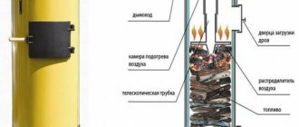
The boiler consists of two metal containers connected by a pipe. A chimney is installed in the upper part, the length of which must be at least a meter. The lower container is intended for pouring waste, where the top layer of oil is heated and turns into oil vapor. Rising, the steam exits into a perforated pipe, mixes with air, reaches the upper container and burns. Combustion products exit through the chimney; thus, the boiler heats the room but does not emit toxic waste.
Waste oil heating boilers
A boiler without a water circuit can easily heat a garage of about 40 square meters. m. As for products with a water circuit, they allow you to maintain a comfortable temperature in fairly large rooms even in severe frosts. Moreover, fuel consumption ranges from 0.5 to 1 liter per hour, which makes it possible to significantly save on energy resources.
Pump heating system
Pump heating system. Circulation pump
The exhaust boiler can be made single-circuit or double-circuit, depending on the needs of the owner. If you use coolant only for heating, you need a single-circuit boiler. The second option allows you to heat the room and obtain hot water for domestic purposes; for this purpose, there is a built-in heat exchanger in the upper tank.
Video - Option of a furnace being tested before connecting the water jacket
The operating principle of such a boiler is also quite simple: from the supply tank, the pump delivers the waste to the evaporation chamber, where it is heated and turned into steam. Steam rises into the combustion chamber, mixes with air and heats the water in the circuit. Hot water enters the pipes and radiators, heats the room and returns back to the boiler.
As practice shows, a waste oil boiler is an effective heating device, and also affordable
As practice shows, a waste oil boiler is an effective heating device, and also affordable
As practice shows, a waste oil boiler is an effective heating device, and also affordable
Features of heating boilers operating on fuel oil
Such heat generators are similar in degree of automation to gas ones, but fuel for them is as common as for coal or wood ones. The combination of these qualities makes this equipment in demand in areas where centralized energy supply is represented only by the electrical network.
Oil heaters are used mainly in industrial boiler houses. Models for private homes are still much less common than diesel models.
Features of the units:
- Energy dependence.
- Electronic automation.
- Turbocharged combustion chamber without communication with the room. Air is sucked into the firebox by a fan from the street through the internal channel of the coaxial chimney.
- Forced exhaust removal, which allows the pipe to be positioned horizontally.
- Work only with closed heating systems equipped with circulation pumps.
Conclusions on consumption calculation 1
Based on the given fuel consumption data, you can estimate the cost of heating for the season.
- We take the heating season to be 6 months, or 180 days.
- For a house of 300 meters, a 30 kW boiler is required (1 kW per 10 meters).
- We choose a boiler from the list above at 34.9 kW, which consumes an average of 12 liters of diesel fuel per day. (10.0-14.5 l).
- The maximum fuel consumption for 180 days will be 180×14.5=2610 liters.
- We understand that no one will heat at maximum the whole season. We assume that for 90 days of the heating season the boiler operates at 100%, and for 90 days at 50%.
- We get: 90×14.5+90×14.5/2=1305+652.5=1957.5 liters.
- Diesel fuel 1957.5 liters costs (retail 38 rubles) 74385 rubles (1240 rubles per month).
In the article “Simplified calculation of the heating system,” I showed the calculation based on the power of the heating boiler. Below there will be another calculation that will show different results.