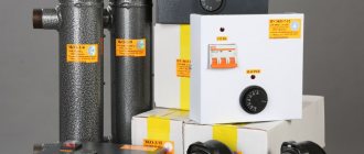
Design and principle of operation of a steam boiler room
Boiler houses can be divided according to the method of heat supplied (hot water, steam, superheated water, thermal oil), by purpose (heating, process), by type of fuel used (gas, diesel, gas-diesel, fuel oil, gas-fuel oil, solid fuel), by design options ( block-modular, roof-mounted, stationary, attached, built-in). The goal of boiler houses is always the same - to generate heat for further use.
Steam boiler houses are boiler houses in which heat is released through the production of saturated or superheated steam by the boiler room. Steam boiler houses are basically always purely industrial boiler houses, in which the further use of steam for production needs is assumed, or for industrial heating, in which, along with the production load, there is a heating load.
A steam boiler room can be made in various versions, it can be a block-modular boiler room, a stationary boiler room, respectively, one or the other option can be made as a free-standing or attached boiler room, depending on the wishes of the Customer and the conditions of a particular enterprise.
A steam boiler house can also operate on different types of fuel, such as gas (natural gas, liquefied gas), diesel fuel, fuel oil, or have two types of fuel: main and reserve, or emergency (gas-diesel, gas-fuel oil). Also, various types of solid fuel (wood waste, coal, etc.) and possibly various types of alternative fuel can serve as fuel.
The boiler room containing steam boilers that use liquid fuel (fuel oil, diesel fuel, various types of oil, waste oil, etc.) must have appropriate fuel storage facilities and installations for preparing this fuel for combustion in the boiler. This basically comes down to heating the liquid fuel so that it can be atomized in the burners for complete combustion in the boiler firebox.
The boiler room containing boilers that use solid fuel (coal, peat, wood waste, etc.), in addition to storing fuel and preparing it for combustion, must have workshops or ash removal plants because It is not possible to burn completely solid fuel. In addition, great attention must be paid to cleaning flue gases from combustion products, or more precisely from products of incomplete combustion of fuel (soot, etc.). “Cuenod” France, “Ecoflam” Italy, “Weishaupt” Germany, “Saacke” Germany, “ Dreizler" Germany, "Cib Unigas" Italy; pumping and heat exchange equipment, automation and safety systems.
All supplied equipment has certificates of conformity and permits for industrial use in the Russian Federation.
Steam boiler houses produced by our company, at the request of the Customer, can be manufactured to operate in automatic mode and can be operated without the constant presence of maintenance personnel. Control of the operation of the boiler room is carried out directly by the boiler room automation (all information is displayed on the control panel installed in the boiler room) plus a general alarm signal or a group of signals is transmitted to the control panel located outside the boiler room via telephone, GSM or Internet connection.
A steam boiler should be understood as a special device that has a firebox in which fuel combustion occurs. The result of this process is heat generated to produce high pressure steam. This steam can be used for a variety of purposes.
What is a steam generator? For what purposes is it needed? And what is the operating principle of a steam boiler?
Service
Repair and maintenance of steam boiler rooms is carried out in accordance with legislative standards and recommendations of industrial steam boiler manufacturers, strictly in accordance with industry and production instructions, as well as in accordance with the rules for the design and safe operation of steam and hot water boilers.
PC maintenance generally includes the following types of work:
- Scheduled inspections of boiler equipment performance according to schedule.
- Determination of boiler malfunctions: overheating, fires, clogging.
- Elimination of violations of fire safety rules and conditions that impede safe operation.
- Checking the integrity of steam-gas systems with subsequent elimination of faults in the fittings.
- Checking the boiler feed system.
- Checking the density of the gas-air path and the absence of non-system noise in the furnace.
- Medical examination and testing of auxiliary equipment.
- Checking the operation of instrumentation and automation, differential pressure gauges, security and alarm systems.
- Monitoring the operation of pumps, smoke exhausters, fans and checking their control units.
- Checking the operation of electrical equipment and automatic protection.
- Checking the operation of the boiler set.
- Checking the operation of water treatment devices and the deaerator of a steam boiler room.
The Russian market has enough offers from both domestic and foreign manufacturers of modern steam boilers; the choice is determined by the design specifications so that specialists can select the optimal equipment options.
Structural elements of a steam boiler and ensuring the safety of working with a steam boiler
The structural elements of a steam boiler include cylinders and vessels of various sizes and diameters, pipes connected to each other into an integral system by means of rolling and welding joints. Absolutely any steam boiler has pipelines, a drum and manifolds. Repair of a steam boiler, its inspection and cleaning are carried out through manholes - special technological openings.
The capacity of the steam boiler, which is filled with water and located inside, is called the water space. The vapor space should be understood as the space that is filled with the resulting steam. The vapor and water spaces are separated from each other by a surface called the evaporation mirror. The steam space contains equipment designed to separate steam and moisture.
The operation of a steam boiler is accompanied by constant and intensive cooling of the metal elements of the entire structure, which are exposed to high temperatures during operation. This allows for safe operation of the steam boiler. Cooling occurs as a result of regular circulation of the coolant through the heating pipes.
Heat from the gases that are formed as a result of fuel combustion enters the pipeline. Meanwhile, the coolant, without stopping, removes heat from the pipeline walls, thereby preventing overheating of the pipeline. If this whole process is not intense enough, the pipeline can overheat greatly, resulting in losing its strength characteristics. Overheating of the pipeline can lead to melting of the pipes or even their rupture. Such phenomena can cause an emergency shutdown of the steam boiler.
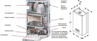
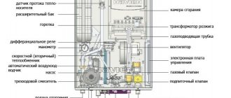
Steam boiler diagram
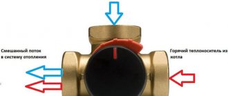
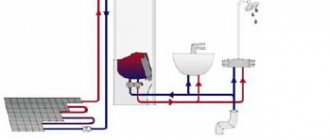
Coolant flow diagram
PCs are installed in the boiler room, which can be located in separate, adjacent and built-in non-residential buildings.
Designations according to the diagram:
- Gas steam boiler fuel supply system, No.1.
- Combustion device - firebox, No2.
- Circulation pipes, No.3.
- Zone of steam-water mixture, evaporation mirror, No.4.
- Direction of feed water movement, NoNo5,6 and 7.
- Partitions, No8.
- Gas flue, No.9.
- Chimney, No.10.
- Output of circulating water from the steam boiler tank, No.11.
- Purge water drain, No.12.
- Boiler top-up with water, No.13.
- Steam manifold, No14.
- Steam separation in the drum, NoNo15,16.
- Water indicator glasses, No17.
- Saturated steam zone, No.18.
- Steam-water mixture zone, No.19.
Steam boiler - operating principle
The operating principle of the steam generator is quite simple. The operation is based on the heat exchange of steam, water and flue gases. There is a classification of thermal boilers according to the method of movement of heat exchange media. There are two types of boilers: water-tube and fire-tube units. The operating principle of a fire tube boiler is as follows: the heated gas moves inside the pipes, and the water that will be heated is located outside the pipes.
The operating principle of water-tube steam boilers involves the movement of water through pipes. The water heats up as a result of the exposure of the pipes to external flue gases. Due to this effect, the water reaches a boiling state.
Boiler steam equipment is classified depending on the movement of water and steam in them. So, there are boilers with natural and forced circulation. Forced circulation involves the movement of coolants under the influence of pumps specially designed for this purpose. Steam boilers with natural circulation operate as a result of the difference in the densities of steam and water.
In general, the operation of a steam boiler is always approximately the same. It consists of the following: water is prepared in a deaerator, after which, using a pump, it is supplied to the water economizer system, where the water is heated as a result of exhaust gases. Next, the water moves into the upper drum and mixes with the boiler water. Part of the heated water from the boiler enters the lower drum through the boiling pipeline. Here a so-called steam-water mixture is formed. As a result, this mixture rises through the lifting pipeline into the upper drum.
The water remaining in the upper drum descends through lower pipes, which are located outside the furnace, to the collector system of screen pipes. In this case, the steam mixture again ends up in the upper drum of the boiler. The pipeline system that carries out the movement of the coolant should be called a circulation circuit.
The steam that is generated in the evaporators then passes through the so-called steam separators, which are an essential component of fire-tube steam boilers. This is where droplets of moisture are released from the steam. After the steam becomes dry, it flows to the superheater through a steam line. Here the steam is heated to the required temperatures.
Operating principle
All types of steam boilers have common elements:
- Drum.
- Drop pipes.
- Collector.
- Flame tubes.
- Separator.
- Steam heater.
The drum is connected to the manifold by lowering and flame pipes. The downpipes do not heat up. Flame tubes are placed in the firebox, and depending on the stage of fire development, a certain amount of steam is formed in them, which does not yet have operational characteristics. The separator is located in the drum, and the steam heater is attached to the drum.
The operating principle of a steam boiler for heating a house is to produce steam with the required characteristics. The operation of the unit with automatic regulation of pressure balance and power development consists of the following stages:
- Cold purified water enters the drum.
- Afterwards it moves through the downpipes into the collector.
- Then it enters the flame tubes. Fire with flue gases heats their outer surface, thereby heating the water to boiling point. Steam begins to form in it. Its characteristics are not yet working.
- The liquid with steam, which still has non-working characteristics, is returned to the drum. The steam moves upward and, passing through the separator, is separated from the water.
- The condensate is returned to the drum, and the steam is supplied to the superheater, where it receives increased characteristics. As a result, there is a significant increase in pressure, productivity, and the efficiency of the boiler installation increases.
- Superheated steam at high pressure is supplied to the heating network.
The operating principle of an electric steam boiler is almost the same. It heats water to a temperature of 100 °C. Its structure does not have lowering or flame pipes because the drum is located in the middle of the collector. Manufacturers call the drum an internal chamber and the collector an external chamber.
During operation of the electric automatic unit, water first enters the outer chamber, and then into the inner one, at the top of which there is a separator. The water is heated by a plate electrode.
Boiler operation monitoring
Companies that produce steam boilers must equip the equipment with special control and measuring devices and instruments that allow monitoring the operation of the steam boiler.
The water level in the system can be adjusted using a water meter glass. The water meter glass is an important element of the control system. It is located on the front panel of the firebox casing. This glass is equipped with special taps: lower and upper. The lower one is located at the upper level of the fire box, and the upper valve is installed inside the steam space of the boiler. The taps are connected to each other by a special glass tube and flat glass. This glass is filled with water using the bottom tap and is always under steam pressure coming through the top tap. This device operates on the principle of the law of communicating vessels. This means that the water level in the boiler will always be equal to the water level in the glass vessel.
The water level during boiler operation should always be between the minimum and maximum levels. The minimum level is set to prevent overheating of metal elements. Many models imply a lower water level of at least 100 mm above the fire zone. To prevent water from entering the steam pipeline system, set the maximum level. If water does get into the steam line, it may experience water hammer, which will lead to a serious accident.
The operating principle of industrial and domestic boilers is approximately the same, and their design is very similar. The so-called waste heat boilers are slightly different. Such boilers heat water with the thermal energy of gases emitted by gas turbine units, diesel generators and other equipment. The design of such a boiler is noticeably different from a conventional steam boiler. Secondary gases in the waste heat boiler immediately flow to the heating surface. This boiler does not have an air heater or firebox. Gases with temperatures from 350 to 700 degrees Celsius enter the boiler. As a rule, such equipment is intended for industrial purposes and is installed in large energy-intensive industries.
How to use it correctly
Steam boilers are classified as high-risk objects, therefore, many boiler inspection regulations, installation designs, technical documentation of the manufacturer and rules for the design and safe operation of steam and hot water boilers set out requirements for the safe operation of such vessels, which are required to be followed by responsible officials and maintenance personnel.
Safe operation begins with chemical water treatment, which is essential for the maintenance of modern steam generators and boilers. Mineral salts contained in natural water, at temperatures above 70 ° C, form scale on the internal surfaces of pipes.
This leads to a deterioration in heat transfer from flue gases to feed water; it stops cooling the pipes, which overheat and burn out, resulting in a wall rupture, a sharp drop in pressure in the internal circuit of the unit, instantaneous vaporization of superheated water and a boiler explosion.
The level of raw water purification depends on the source of water supply and is established by specialists in the water treatment project of the boiler unit, which describes not only the modes, but also the connection diagram with the necessary equipment.
Boiler control can be manual or automated. Modern PCs without automation and security protection are not allowed for operation. Manual control with safety protection is only permitted in low-power, low-pressure coal-fired boilers.
Boiler control structure:
- Devices for ignition and shutdown of fuel combustion.
- Cost regulation: fuel, air and water.
- Collection and analysis of PC operation data.
- Boiler emergency stop system.
Once-through boilers
In addition to boilers with natural and forced circulation, there are also so-called direct-flow boilers. The design of such boilers does not have a drum. The water passes through the evaporator line once, gradually turning into steam. In the transition zone, the process of converting water into steam is completed. The steam-water mixture from the evaporation pipeline enters the superheater, where the steam is heated to the required temperature. Some once-through boilers have an intermediate steam heater. It is designed to reheat the steam that came from the turbine unit. Having warmed up again, the steam returns to the turbine. A once-through boiler represents a so-called open hydraulic system. Such a boiler plant can operate at both subcritical and supercritical pressures.
Once-through steam boilers do not require specially equipped premises. They do not require regular operation and technical supervision.
The most important and undeniable advantage of a direct-flow steam boiler is the minimum time required to heat water and the short period of time required to bring the boiler into working condition. Due to all these advantages, once-through boilers serve as backup units, the use of which is necessary in case of failures and during loads of the main boiler equipment.
In addition, once-through boilers have other advantages. Firstly, they allow a higher thermal load. Secondly, there are no heavy and bulky collector installations; it is possible to freely arrange the heating surfaces. The heating surface is used most effectively. Once-through boilers have high efficiency and are quite compact, with high maneuverability.
Signs that there is not enough water in the heating system
Operating personnel or the owner of the boiler unit must accurately determine the deficiency of coolant in its circuit. First of all, using a pressure gauge, since the pressure of the medium in the network will drop if there is a leak.
In modern autonomous systems equipped with multifunctional automation, water leakage from the heating network is included in the mandatory indicator for boiler protection, therefore, if it falls, the personnel will be warned by alarms: audio and visual.
For older modifications of the boiler, a drop in coolant pressure due to unproductive leaks is determined by the following criteria:
- overheating of the supply coolant, despite the fact that the radiators quickly cool down due to disruption of water circulation in them;
- the water in the network begins to gurgle, especially in heating risers;
- the boiler clocking process begins, when the burner of the gas unit is often turned on/off;
- activation of the safety valve of a solid fuel boiler due to overheating of the coolant.
The situation with leaks is especially dangerous in solid fuel boilers, since due to the high inertia of the combustion process, the boiler cannot stop until all the stored fuel has burned out, which means there is a high possibility of overheating of pipes or heat exchangers located in the firebox, with their subsequent rupture and leakage open fire source in the furnace room.
Disadvantages of once-through boilers
The disadvantages of a direct-flow steam boiler include too frequent switching on of the burners compared to a fire-tube boiler. There are also no accumulating steam and water tanks here. Despite the fact that this problem can be solved with the help of controlled fuel supply, this can lead to the burners turning on even more often, and the load mode will fluctuate, which will lead to premature wear of the equipment.
In addition, as a result of constantly turning the burners off and on, soot is released, which is deposited on the heating surface and requires removal. In this case, much more fuel is consumed.
The choice of once-through boilers is now quite large. They differ in their power and models. The choice of a steam boiler should be based on the goals and objectives of the equipment.
The rapid development of agriculture and production requires modern high-tech equipment. However, in order to ensure a full production cycle and create comfortable working conditions for employees, specialized equipment for space heating is needed.
Steam boilers are designed to solve these problems. They are actively used in all areas of human life, where it is necessary to constantly maintain a given temperature.
Operating principle of the boiler
To understand what a steam boiler is, let's look at its structure and operating principle. The purpose of using the unit in question is to generate steam. The process occurs due to the formation of heat during the combustion of fuel or heating of tubular electric heaters, and the temperature of the steam boiler liquid reaches the desired level.
The working composition of a steam boiler is water. When it heats up, it goes into a vapor state. The industry produces small boilers with a productivity of up to 20 kg/h and industrial units producing up to 5 thousand tons of steam in one hour.
A steam boiler is a drum filled with water, under which there are lowering pipes necessary for the flow of water into the collectors.
The entire boiler system is technologically connected to each other by pipes. Due to the fact that they contain a mixture with a density lower than the density of water, it rises into the separator. In it, the mixture is divided into liquid and steam, while the steam enters the steam lines and water heater and is supplied to the turbine, and the liquid is returned back to the drum.
The unit consists of:
>Steam pipelines; >Water heater; >Hulls; >Economizer; >Sheathing.
All modifications of boilers have a furnace in which fuel is burned. The resulting heat is absorbed by water, which, upon reaching the desired temperature, evaporates. A process of natural circulation is observed. The products of fuel combustion cool down and are discharged through the chimney.
The body of the unit in question has external thermal insulation and casing in the form of a split steel casing. The water heater allows you to increase productivity and consists of smoke pipes in which water is heated due to the heat of exhaust gases.
There is a safety valve at the bottom of the unit that releases steam if the operating pressure exceeds the permissible limit. The boiler equipment also includes a manual and steam jet injector. The first is necessary for filling with liquid at the beginning of work, as well as for replenishment in the event of a breakdown of the steam jet injector.
To facilitate operation, steam boilers are equipped with automated control systems.
Hello student
The feed system closes the boiler-turbine steam power cycle, providing the possibility of returning exhaust steam to the boiler in the form of feed water. This system has four main elements: boiler, turbine, condenser and feed pump. The boiler produces steam, which is fed to the turbine, and after the steam has consumed energy, it is sent to the condenser. There the steam turns into water (condensate), which is supplied by a feed pump to the boiler.
In practice, the system also includes a number of elements, such as a waste tank, into which condensate from the condenser is discharged and thanks to which a certain pressure is provided at the inlet to the feed pump. To compensate for water leakage from the system or to create some excess feed water in the system, a compensation tank is provided. If the feed system serves an auxiliary boiler, for example, on a ship, then the waste tank or warm box communicates with the atmosphere. Such a system is called open. In high-pressure water-tube boilers, the feed system in no part communicates with the atmosphere, and such a system is called closed.
OPEN NUTRIENT SYSTEM
A diagram of the open feed system for the auxiliary boiler is shown in Fig. 5.1. Exhaust steam from various auxiliary mechanisms is condensed in a condenser, which is cooled by sea water. The pressure in the condenser can be maintained at atmospheric or slightly below atmospheric. The condensate from it flows into a warm box equipped with filters. If the condenser is operating under a slight vacuum, a condensation pump is used to supply water to the warm box. The warm box may also receive condensate from systems in which it can become contaminated, for example from fuel heaters, from the fuel heating system in tanks, etc. Contaminated condensate can be detected either at the outlet of the condensate cooler, or by monitoring the control tank.
Rice. 5.1. Open feeding system:
1 - nutrient tank; 2 - pipeline for draining excess water: 3 - warm box with filters; 4 - capacitor; 5—valves for supplying steam to mechanisms and devices;
6 — feed water regulator; 7 - boiler; 8 — auxiliary feed pump; 9 — main feed pump; 10 — feed water heater
A monitoring tank, if installed, allows such monitoring and if contaminated condensate is detected, it is directed to the contaminated wastewater tank. The warm box contains deflectors for preliminary separation of oil or fuel from condensate or feed water. The water is then passed through carbon or fabric filters to complete the purification. Excess water from the warm box is transferred to the feed water tank, from where the feed system will be replenished if necessary. Water is drawn from the warm box by the main and auxiliary feed pumps. A feedwater heater can be installed in the main feed system. The heater can be a surface type, in which only water is heated, or a contact type, where in addition to heating the water, it is also deaerated. Deaeration is the process of removing air containing oxygen from feed water, the presence of which can cause corrosive processes in the boiler. To regulate the water supply to the boiler and maintain the required level in it, a feedwater regulator is installed.
The system described above is a typical system, and there may be some differences in each specific installation.
CLOSED NUTRIENT SYSTEM
In Fig. Figure 5.2 shows a diagram of the closed feed system of a high-pressure water-tube boiler supplying steam to the main steam turbine.
Steam from the turbine enters the condenser, where a high vacuum is maintained. A regenerative type condenser is used here, in which condensation is carried out with a minimum temperature difference. The condensate pump pumps condensate out of the condenser and delivers it to the air ejector.
Passing through the ejector, the condensate is heated. The air ejector, which serves to pump air out of the condenser, is a steam jet ejector.
Rice. 5.2. Closed nutritional system:
1 — feed water tank; 2 condensate pumps; 3— capacitor; 4 - pipeline for air and gases; 5 — air ejector; 6 — sealing system capacitor; 7 - recirculation pipe; 8— valves for supplying steam to mechanisms and devices; 9 — drainage condensate cooler; 10 — low pressure heater; 11—economizer; 12 - boiler; 13 — steam superheater; 14 — high pressure heater; 15 — feed pumps; 16 — deaerator; 17—drainage pump; 18 - atmospheric waste tank
The condensate is then passed through the sealing system condenser where it is further heated. This condenser condenses the steam from the turbine seal system and drains the condensate into the waste tank. Next, the main system condensate passes through a low-pressure heater, which is fed by steam from the turbine extraction. The use of all of the above heaters improves the efficiency of the installation due to regenerated heat, and the increase in water temperature contributes to its deaeration.
In the deaerator, direct contact of feed water with steam occurs, where they actually mix. When mixed, the water is heated and all dissolved gases, in particular oxygen, come out of it. The lower part of the deaerator is a container from which water is taken directly by one of the feed pumps that supplies water to the boiler.
The water then flows to the high pressure feedwater heater, then to the economizer, and from there to the steam header. The system has a waste tank connected to the atmosphere to drain excess feed water into it and a feed tank, from where, if there is a lack of water, the feed system will be replenished. The waste tank also receives condensate from many auxiliary systems, such as the turbine seal system, condensate from the exhaust working steam of air ejectors, etc. To ensure the passage of feed water through the air pump and seal system condenser at low power conditions and during maneuvering of the vessel in The system is equipped with a recirculation jumper.
This diagram is also typical, and there may be some differences in it for each specific installation.
AUXILIARY NUTRITION SYSTEM
The system is designed to generate steam from condensate from auxiliary mechanisms and devices; it can be performed either separately - in the form of an open or closed system, or in conjunction with the main supply system, forming part of it.
In cases, for example, when deck mechanisms use a steam drive, a condenser operating at a pressure close to atmospheric is used to condense the exhaust steam (Fig. 5.3). The condensate is supplied by a condensate pump to the air ejector, after passing through which the water enters the main supply line between the sealing system condenser and the drainage condensate cooler. For operation at low power, recirculation is provided, and to regulate the water level in the condenser there is a level regulator.
Rice. 5.3. Auxiliary nutritional system:
1 - level regulator; 2—recirculation pipe; 3 - auxiliary capacitor; 4 — air ejector 5 — condensate pump; 6 — drainage condensate cooler; 7 — sealing system capacitor; I - supply of exhaust steam from auxiliary mechanisms and devices
Rice. 5.4. Steam generator feed system:
1 — feedwater heater; 2 — steam generator; 3 - pipeline for low pressure steam; 4 - valves for supplying steam to auxiliary mechanisms and devices; 5 — tank of contaminated condensates; 6 - feed pumps; I—discharge of condensate into the main feed system; II - steam supply
If there is a risk of contamination of the feedwater in the installation, a separate system can be created for the steam generator (Fig. 5.4). Low pressure steam from the steam generator is supplied for various ship needs, such as fuel heating, and the condensate is returned to the warm box. Feed pumps supply water to the feed water heater, which simultaneously serves as a cooler for the condensate obtained from the heating steam of the steam generator. From here the water goes directly to the steam generator.
Many companies produce nutritional systems in a modular design, that is, various elements of the system are mounted on a single foundation. Sometimes the entire set of mechanisms and devices or some part of it is located there.
ELEMENTS OF THE NUTRIENT SYSTEM
Capacitor.
This is a heat exchanger in which latent heat is removed from exhaust steam, as a result of which the steam turns into condensate, which is sent back to the boiler. Condensation should be carried out with minimal subcooling, i.e. the temperature of the condensate should differ minimally from the temperature of the steam. The condenser is designed in such a way that various gases and vapors that are released during condensation of water vapor are removed from it.
In Fig. Figure 5.5 shows an auxiliary capacitor. The body, round in cross-section, is closed on both sides with lids designed so that the sea water in the condenser makes two passes. Protectors are installed in the water cavities of the covers, which are necessary to protect against electrochemical corrosion. Steam enters the condenser from above in the central part of the housing and through the windows in the inlet box located under the casing, it is divided into two streams. Steam condenses on the surface of the tubes through which sea water passes. To fasten the tubes, a diaphragm is arranged along the length of the middle of the condenser, which in turn is secured using anchor bolts. Condensate accumulates in a sump located under the bundles of water tubes. Provision is made for pumping out air, gases and vapors released during condensation of water vapor.
The main condensers operating in conjunction with the main steam turbines are regenerative type condensers. Part of the steam in them passes through the tubes and comes into contact with the condensate in the sump. The condensate thus has the same temperature as the steam, which increases the efficiency of the condenser. In Fig. Figure 5.6 shows one of the regenerative capacitor projects. In its center there is a channel through which steam passes to the settling tank and, condensing, heats the condensate.
Rice. 5.5. Auxiliary capacitor:
1 — condensate return pipe; 2 — protectors; 3 - manhole with inspection hatch; 4 - anchor bolt; 5 — inlet water box; 6 — flange for supplying circulating water; 7 — inspection hatches; 8 — water drainage flange; 9 — plugged fitting; 10 — casing at the steam inlet to the condenser; 11 — wet steam inlet pipe; 12 — pipe from the boiler top blowing valve; 13, 27 — pipes for the thermometer; 14. 30 - pipes for the tap of alkaline additives; 15 - air valve; 16 — pipe for a vacuum gauge; 17 — water box; 18 — spare steam pipe; 19 — capacitor body; 20 - water measuring glass; 21—sump; 22 — air exhaust pipe; 23 - diaphragm; 24 - tube plate; 25 dividing partition; 26— drain plug; 28 — drain valve pipe; 29 condensate exit cabins
rice. 5.6. Regenerative type capacitor:
1 - tubes; 2 — capacitor body; 3—gas and air suction pipe; 4 - outlet partition; 5 - central channel; 6 — condensate level; I—exhaust steam; II - steam to the condensate drain pump
There are partitions for the released gases and vapors. A plurality of tubes are installed in the tube sheets on both sides, supported by intermediate supports. The intake water in the tubes makes two passes.
Condensate pump.
This pump is designed to pump water from a condenser in which a vacuum is maintained. At the outlet of the pump, pressure is created to supply water to the deaerator or to the feed pump. By design, condensate pumps are usually centrifugal, two-stage, with a vertical shaft. The design of the pumps is described in Chapter. 6. For normal operation of these pumps, a certain minimum suction head is required, as well as a certain controlled level of condensate in the condenser. The first stage of the pump receives water, which almost boils under the vacuum conditions that exist in the suction pipe. Water enters the second stage with some positive pressure, and at the exit from the second stage the water has a given pressure.
In condensers where the condensate level may fluctuate or where the sump is almost dry, self-regulating condensate pumps can be used. Self-regulation in them occurs during cavitation, which occurs when the suction pressure drops to a very small value. Cavitation is the process of formation and destruction of steam bubbles, as a result of which the pump flow drops to zero. As the suction pressure increases, cavitation disappears and the pump begins to supply water again. During cavitation, various damages usually occur (see Chapter 11), but at the low pressure that exists in condensate pumps, no damage is observed. In addition, the pump impeller can be designed in such a way that supercavitation will occur, i.e., the destruction of bubbles after they exit the impeller.
Air ejector.
Using an air ejector, air and vapors are sucked out from the steam condensing in the condenser. If air is not removed from the system, corrosion may occur in the boiler. In addition, the presence of air in the condenser would complicate the condensation process and lead to the creation of back pressure in it, due to which it would be necessary to increase the steam pressure at the turbine outlet, which leads to a decrease in thermal efficiency.
In Fig. Figure 5.7 shows a dual two-stage air ejector. In the first stage, this steam jet ejector acts as a pump, sucking air and gases from the condenser. Then the steam-air mixture enters the condensing part, where feed water circulates. The feedwater is heated and most of the vapor is condensed. The condensate from here descends into the main condenser, and the vapors and gases pass into the second stage of the ejector, where the process is repeated. The remaining air and gases after passing through this stage are released into the atmosphere through a vacuum check valve.
Rice. 5.7. Air ejector:
1—rolled pipe ends: 2—spacer tube: 3—anchor bolt; 4 - first stage capacitor; 5 — capacitor body; 6 — sliding support; 7 — steam nozzle of the first stage; 8 — nozzle holder; 9 — steam nozzle of the second stage; 10—separating partition: 11—second stage capacitor; 12 — condenser tubes; 13 — water box partition; I, II - air inlet and outlet: III, IV - cooling water inlet and outlet
Rice. 5.8. Drain condensate cooler:
1 — box cover; 2 - distribution box, 3 - air valve: 4 - safety valve; 5 - pressure gauge; 6 — U-shaped tubes; 7 - anchor bolts; 8 — support paw; 9 — body; 10 - diaphragm; 11— drain valve; 12 — dividing partitions; I—condensate outlet; II - steam inlet; III, IV - feedwater outlet and inlet
Feedwater in both stages circulates through U-shaped tubes. Each stage has two ejectors, although the operation of one of them is sufficient for satisfactory operation of the installation.
Heat exchangers. The compaction system condenser, drain condensate cooler, and low-pressure feedwater heater are all tube-type heat exchangers. In each of them, in one way or another, heat is removed from the exhaust steam and, thanks to this, the feed water circulating in the tubes of the apparatus is heated.
The condenser of the turbine sealing system receives steam, gases and air, which are cooled by water, and the steam condenses. The condensate is returned to the system through a loop water seal or steam trap, and the remaining air and gases are released to the atmosphere. The feedwater in the heat exchanger flows through U-shaped tubes.
Exhaust steam from various auxiliary mechanisms and devices enters the drain condensate cooler, in which the steam is condensed and the condensate is returned to the feed system.
1—water; 2 - steam; 3—water jets; 4 — neck cover; 5 — air pipe pipe; 6 - inlet water manifold; 7 — nozzles; 8 — partition of the upper water-cooling chamber; 9 — partition of the lower water-cooling chamber; 10 — guide cone; 11 — deaerator cones; 12 — body; 13 - guide; 14 — manhole cover; 15 — paws; I— water drain; II - steam supply; III—water supply.
Circulating feed water passes through the apparatus through straight tubes fixed in tube sheets. Diaphragms and partitions serve to direct the flow of steam in the apparatus and at the same time to fasten the tubes (Fig. 5.8).
The low-pressure feedwater heater typically receives steam from the low-pressure turbine exhaust. Heating the feed water promotes the deaeration process. By extracting steam from the low-pressure turbine, not only does the thermal efficiency of the installation improve, but it is also possible to reduce the height of the blades of the last stages, since the mass of the steam flow is reduced. These devices can use both straight and U-shaped tubes, and in the water part the tubes can be single-pass or multi-pass.
Deaerator.
The deaerator completes the process of removing air and vapor from the feed water, which began in the condenser. At the same time, the deaerator also serves as a feedwater heater, but in it the water and heating steam come into direct contact. The feed water is heated to a temperature close to the boiling point, at which all dissolved gases are released from it, and these gases are immediately removed.
In Fig. Figure 5.9 shows one of the deaerator designs. Feed water is supplied to the deaerator through several spray nozzles. The sprayed water has a very large contact surface with the heating steam. Most of the water falls from above onto the surface of the upper cone, where the process of heating it with steam continues. Then the water enters the central channel and leaves it through a small hole, which acts as an ejector that sucks in steam along with water. Feed water and working steam condensate accumulate in a storage tank that makes up the lower part of the deaerator. The working steam enters the deaerator, passes through it, heating the feed water, and, turning into condensate, mixes with the feed water. The released gases exit through the air pipe into the steam-air mixture condenser. The steam that gets there along with the air condenses and returns to the system. Feed water circulates in the tubes of the steam-air mixture condenser, and from there it immediately enters the deaerator.
The temperature of the feed water in the deaerator is very close to the temperature of the steam at the pressure existing in the deaerator, and therefore it is possible, with any drop in pressure, to instantly convert water into steam. This can lead to “gassing”, i.e. the formation of steam in the suction part of the feed pump. To avoid this, the deaerator is located in the upper part of the engine room, thereby providing a certain positive pressure at the inlet to the feed pump. But sometimes a pump-out or booster pump is installed directly at the outlet of the deaerator.
Feed pump.
Designed to create feedwater pressure at which it enters the boiler. For auxiliary boilers that consume a small amount of feed water, a steam-driven piston pump can be used as a feed water pump. A pump of this type is described in Chap. 6. Another type of pump that is often used in packaged boiler installations is the electric feed pump. This is a multi-stage centrifugal pump driven by a DC motor.
In installations with high-pressure water-tube boilers, turbine-driven feed pumps are used. Shown in Fig. 5.10, a two-stage horizontal centrifugal pump driven by an active turbine is placed in a common housing with it. Steam to the turbine comes directly from the boiler and exits into the main line, from which the steam can be directed to heat water. The pump bearings are lubricated with filtered water, which is taken after the first stage of the pump. The pump is equipped with a regulator to maintain the set pressure and a limit switch that is activated when the rotation speed is exceeded.
Rice. 5.10. Turbine driven feed pump:
1 — steam outlet flange; 2— messenger valve socket; 3— release mechanism of the limiting speed regulator; 4— turbine disk; 5 — turbine shaft coupling bolt; 6 — replaceable cover, 7 — Hirs coupling; 8 - partition; 9 — nozzle box; 10—pipe to the pressure gauge in the nozzle; 11 — Venturi tube; 12 — water discharge pipe; 13 — load of the limiting speed regulator; 14 - shaft; 15 — balancing piston; 16 — ring section; 17 — pump impellers; 18—pipe to the water pressure gauge on the receiving water pipe; 19 — channel to the balancing piston; 20 — receiving water pipe; 21 - water intake; 22 — cocking lever for the maximum speed regulator; 23 — emergency shutdown handle
High pressure feed water heater.
The heater is a tubular type and is used for additional heating of feedwater before entering the boiler. Since the water pressure after the feed pump increases, it becomes possible to additionally heat the water without boiling it. The water entering the heater circulates through U-shaped tubes, washed by heating steam. There are diaphragms that serve to secure the tubes and to direct the flow of steam inside the apparatus. To ensure complete condensation of the steam, a condensation trap is installed. Steam from the turbine exhaust is used as a heater.
Maintenance of the nutritional system.
During continuous operation of the installation in operating mode, it is necessary to maintain equality of the masses of feed water introduced into the boiler and the steam leaving it, while the water level in the boiler must be maintained within normal limits.
Protectors made of low-carbon steel are installed in the water cavities of the condenser covers, where sea water passes. They need to be replaced periodically. At the same time, the tubes are inspected to detect erosion, which may occur if the circulation rate is very high. Leaks in the water tubes can lead to contamination of the feed water, so if there is even the slightest suspicion of a leak, the capacitor should be tested. In ch. 7 shows the scope and content of work when testing capacitors.
Condensate pump seals should be checked regularly to prevent air from entering the system. For all types of pumps, a small amount of water leaking through the sealing device to help lubricate the bearing and seal is acceptable and normal.
An air ejector will experience reduced performance if its nozzle becomes coated or eroded, so the ejector nozzles should be inspected regularly and replaced if necessary. You also need to periodically check the tightness of the ejector housing and the tightness of the vacuum valve.
You should periodically check for leaks in the heat exchangers and ensure the cleanliness of the heat exchange surfaces.
Turbine-driven feed pumps must be started with the discharge valve closed so that the pressure in the discharge line rises sharply and hydraulically equilibrates with the pressure in the boiler. Turbine drives of pumps must be warmed up before operation with the drain valves open and put into operation after the drain valves are closed. It is necessary to regularly check the operation of the load limit regulator. It is also necessary to control the axial clearances in the turbine, for which special probes are used.
Download abstract: You do not have access to download files from our server. HOW TO DOWNLOAD HERE
Archive password: privetstudent.com
Classification of steam boilers
Depending on the method of heating the coolant, gas, solid fuel and electric steam boilers are distinguished.
Gas-fired steam boilers are characterized by the power to produce saturated steam, measured in kg/h. The main characteristics of the unit are temperature and steam pressure.
Steam gas boilers can use natural or liquefied gas as fuel. The fuel burns in a burner installed on the boiler lid. Flue gases increase the temperature of the water, as a result of which it turns into a vapor state and is supplied under pressure to consumers through an installed steam separator.
A steam hot water boiler can also use wood as fuel. The operating principle of wood-fired steam boilers is based on the heat exchange between the coolant and flue gases. Firewood burns in a firebox surrounded by a cooled water jacket. Flue gases overcome the heat exchanger and exit from the top of the unit. When the heated coolant evaporates, steam is formed. It accumulates on top of the boiler, in the steam collection chamber, and is sent to production needs through a steam pipeline.
Electric-type steam boilers differ from the other two types in their compact size. This allows the steam hot water boilers in question to be installed on the wall.
Currently, electric-type steam water-heating boilers are the most popular, since they do not require the organization of a separate boiler room with a chimney, do not burn oxygen, and have simple controls.
Repair features
Drum-type boilers are characterized by reliable operation and unpretentious operation, but they require constant monitoring to ensure stable heating modes and steam pressure, as well as timely purge. If one of these requirements is not met, breakdowns may occur and the need to repair the unit arises.
Before carrying out repair work, it is imperative to study the documentation supplied by the manufacturer and the diagram of the drum boiler. This will allow you to determine the sequence of all actions and prevent mistakes that could cause more serious consequences.
To repair the drum, you must adhere to the following recommendations:
- Before restoration begins, the condition of the metal should be assessed: thickness, strength, tightness;
- detected defects must be ground with an abrasive tool to bare metal so that it can be welded or patched;
- searching for cracks by heating the surface with a torch is strictly prohibited, since there is a high risk of deformation of components or loss of steel properties;
- corrosion to a metal depth of up to 10% may not be eliminated, but only plugged with cement mortar;
- to restore the thickness of steel, electric surfacing is used;
- welding of shells is mandatory, provided their dimensions are up to 40 mm and a distance equal to three sizes of the largest of them (if the depth of damage is more than half the thickness of the walls).
Definition
As you already understand, a steam boiler is a unit that produces steam. In this case, boilers of this type can produce two types of steam: saturated and superheated. In the first case, its temperature is about 100 degrees, and the pressure is about 100 kPa. The temperature of the superheated steam rises to 500 degrees and the pressure to 26 MPa. Saturated steam is used for domestic purposes, mainly for heating private houses. Superheated steam has found application in industry and energy. It tolerates heat well, so its use greatly increases the efficiency of the installation.
For what purposes is steam needed?
Knowing where a steam boiler is used and with what modes allows you to effectively select equipment.
PCs are used in the following industries:
- Housing and communal services in central heating install PC modifications of low or medium pressure for steam heating. The coolant enters either directly into the network, or through heat exchangers it prepares water for central heating and hot water supply.
- The industry uses more powerful steam generators that produce superheated steam with increased heat transfer.
- Energy, high pressure steam boilers are involved in electricity generation schemes by transferring steam to a turbine.
- Industry, PCs provide mechanical movement of production devices.
- Railway transport, PCs are installed on diesel locomotives.
Scope of application
There are three main areas of application for steam boilers:
1. Heating systems. Steam acts as an energy carrier. 2. Energy. Industrial steam engines, or steam generators as they are also called, are used to generate electrical energy. 3. Industry. Steam in industry is used not only to heat the “jackets” of devices and pipelines, but also to convert thermal energy into mechanical energy and move vehicles. Domestic steam boilers are used for heating residential premises. In simple words, their task is to heat water and move steam through the pipeline. Such a system is often installed together with a stationary stove or boiler. Typically, household appliances produce saturated, non-superheated steam, which is quite sufficient to solve the tasks assigned to them.
In industry, steam is overheated - it continues to be heated after evaporation in order to increase the temperature even more. Such installations are subject to special quality requirements, since if the steam overheats, the container runs the risk of exploding. Superheated steam obtained from the boiler can be used to generate electricity or mechanical movement.
An electric current is generated using steam as follows. Evaporating, the steam enters the turbine, where, thanks to the dense flow, it rotates the shaft. Thus, thermal energy is converted into mechanical energy, which, in turn, is converted into electrical energy. This is how power plant turbines work.
The rotation of the shaft, which occurs when large quantities of superheated steam evaporate, can be transmitted directly to the motor and wheels. This is how steam transport is set in motion. Popular examples of the operation of a steam engine include the steam generator of a steam locomotive or a ship's steam boiler. The principle of operation of the latter is quite simple: burning coal produces heat, which heats water and produces steam. Well, the steam, in turn, rotates the wheels, or in the case of a ship, the screws.
Let's take a closer look at how such boilers work. The source of heat required to heat water can be any type of energy: electric, solar, geothermal, heat from the combustion of gas or solid fuel. The steam generated during the heating process of water is a coolant, that is, it transfers thermal energy from the place of heating to the place of use.
Despite the variety of designs, the fundamental structure and operating principle of steam boilers are no different. The general scheme for heating water and then converting it into steam looks like this:
- Purification of water using filters and its supply to the tank for heating using a pump. The reservoir is usually located at the top of the installation.
- From the reservoir, through pipes, water enters the collector, located, respectively, below.
- The water rises again, only now not through the pipes, but through the heating zone.
- Steam is generated in the heating zone. Under the influence of the pressure difference between the liquid and gaseous substance, it will rise upward.
- At the top, the heated steam is passed through a separator where it is finally separated from the water. The remaining liquid is returned to the tank, and the steam follows into the steam line.
- If this is not an ordinary boiler, but a steam generator, then its pipelines are additionally heated. Methods for heating them will be discussed below.
Features of steam heating
Steam systems have a number of features that should be taken into account during installation to prevent problems during operation.
• Condensate removal in steam systems is carried out in two ways. With closed circulation, the cooled steam is converted into condensate, after which it flows back into the boiler by gravity. To do this, you should take care of the level of installation of the outlet pipe; it should be lower than the level of the radiator. With open circulation, the cooled steam is collected in a special tank, from which it is forcibly pumped into the boiler. The pumping process is ensured by a circulation pump.
• Heating with steam tends to dry out the air in the room, so you should humidify it using special devices or by placing a container of water next to the radiator.
• There is a combined type of boilers, which has a number of advantages. Its installation will allow you to avoid dependence on one type of fuel.
• Radiators should be placed under window openings when drawing up a project. This will help avoid serious heat losses in the room.
Device
Steam boilers are a container in which water is heated and produces steam. They are usually made in the form of pipes of various sizes. In addition to the water pipe, the boiler always has a fuel combustion chamber (furnace). Its design may vary depending on the type of fuel used. If it is firewood or hard coal, then a grate is installed in the lower part of the firebox, on which the fuel is placed. Air enters the combustion chamber from the bottom of the grate. And at the top of the firebox there is a chimney, which is necessary for effective draft - air circulation and fuel combustion.
The operating principle of solid fuel steam boilers is somewhat different from devices that use liquid or gaseous material as a coolant. In the second case, the combustion chamber involves a burner that operates similar to the burners of a household gas stove. A grate and a chimney are also used for air circulation, because regardless of the type of fuel, air is the most important condition for combustion.
The combustible gas obtained from the combustion of fuel rises to a container of water. It gives off its heat to the water and exits through the chimney into the atmosphere. When water reaches its boiling point, it begins to evaporate. It is worth noting that water evaporates earlier, but not in such quantities and not with the same vapor temperature. The evaporated steam enters the pipes on its own. Thus, the circulation of steam and the change in the state of aggregation of water occurs naturally. The operating principle of a natural circulation steam boiler requires minimal human intervention. All the operator needs to do is ensure stable water heating and control the process using special devices.
In the case of electric boilers, heating water is easier. It is heated using heating elements such as heating elements or acts as a conductor and is heated according to the Joule-Lenz law.
Firebox
The main element of the boiler is the furnace, where solid fuel is burned, which is supplied using a coal feeder. If the machine runs on liquid fuel, then it is supplied through nozzles. The high-temperature gases released as a result of combustion transfer heat through the walls of the firebox to water. Then the gases, having given up most of the heat to evaporate water and heat saturated steam, are released into the atmosphere through a chimney and a spark arresting device.
The steam generated in the boiler is accumulated in the steam bell (in the upper part). When the steam pressure reaches above 105 Pa, a special safety valve releases it, releasing the excess into the atmosphere.
Hot steam under pressure is supplied through pipes to the cylinders of the steam engine, where it presses on the piston and connecting rod and crank mechanism, causing the drive axle to rotate. The exhaust steam enters the chimney, creating a vacuum in the smoke box, which increases the flow of air into the boiler firebox.
What is the difference between gas and water tube steam boilers?
The operating principle of boilers is based on heating a container of water. The container in which water turns into a vapor state is usually a pipe or several pipes. Devices in which fuel heats pipes by rising upward are called gas-tube boilers.
But there is another option - when flammable gas moves through a pipe located inside a container of water. In this case, the water tanks are called drums, and the boiler itself is called a water-tube boiler. In everyday life it is also called a fire tube boiler. Depending on the location of the water drums, boilers of this type are divided into: horizontal, vertical and radial. There are also models in which different directions of pipes are implemented.
The design and principle of operation of a fire-tube steam boiler is somewhat different from a gas-tube boiler. Firstly, this concerns the size of the water and steam pipes. Water-tube boilers have smaller pipes than gas-tube boilers. Secondly, there are differences in power. A gas-tube boiler produces a pressure of no more than 1 MPa and has a heat-generating capacity of up to 360 kW. The reason for this is large pipes. In order for sufficient steam and pressure to be generated in the pipes, their walls must be thick. As a result, the price of such boilers is too high. A water tube boiler is more powerful. Thanks to the thin walls of the pipes, the steam heats up better. And thirdly, water tube boilers are safer. They produce high temperatures and are not afraid of significant overloads.
Advantages of using hot water boilers
- High efficiency with the lowest possible fuel consumption.
- The compactness of the device allows you to save on the construction of a boiler room. Often a hot water boiler is installed not even in a separate building, but in the basement of the house that it supplies. In some cases, SNIP rules allow this.
- The design of the water heating boiler is simple; maintenance and repair of the device is not particularly difficult.
- With precise programming of temperature conditions and proper commissioning, the water heating boiler stably maintains the required temperature for optimal heating of the building. In this case, human participation is not required.
Design, principle of operation of hot water boilers
General device:
- Pipes at the bottom (3 pcs.) - for water entry, including for cooling, so that the boiler does not overheat, for filling and draining.
- Air valve - located at the very bottom of the structure.
- The lower damper is a door that covers the firebox.
- Compartment for cleaning from combustion products.
- A lid near the chimney to make cleaning easier.
- Chimney.
- Upper flap.
- Pipe at the top (2 pcs.) - for the outlet of water, including the one that protects against overheating.
Principle of operation:
- Fuel is placed in the firebox.
- Water flows through the receiving pipe.
- Under the influence of high temperatures as a result of combustion, the water in the receiver heats up and rises further through the pipe “artery” to be supplied to the heating system.
- The chimney performs a convection function - it draws out gas and smoke from the combustion of energy.
- The air exchange valve supplies or blocks the supply of oxygen for combustion.
These boilers are typically made from strong but flexible steel that can withstand very high temperatures and pressures.
Coolant: water
Such installations use the cheapest natural coolant - water. They are quite suitable for heating a hangar, warehouse or other large-scale indoor space. But water can create scale inside the system, which improved boiler models can reduce or clean.
Such boilers are usually designed to heat:
- stock;
- residential buildings (utilities);
- production premises (workshop, covered platforms);
- premises of agricultural significance;
- vegetable stores or granaries;
- institutions and administrative buildings;
- other large objects and structures.
Types: fire tube, water tube
The special design advantages of hot water boilers are that you can choose any of two options: fire-tube (or gas-tube) or water-tube.
Characteristics:
- The fire tube model is a special system of tubes supplying heated energy, automatic burners with blowing fan devices. In domestic conditions, these options are not used.
- Water tube model - special boiling tubes move the coolant. Warm up quickly, overloads occur, but explosions are practically excluded.
Types: low temperature, high temperature
There are also boilers of varying levels of combustion and heat transfer. For example, there are options for long-term and short-term combustion, and there are also other types.
Characteristics:
- Low temperature model – up to 115 degrees. Great savings in fuel consumption, but there is also an accumulation of condensate, so careful operation is required.
- High temperature model – up to 150 degrees and above. Reliability is stable, the level of operation is high. Quiet operation, minimal waste emissions, and safety control systems.
Additional boiler elements
The operating principle of a steam boiler is quite simple, however, its design consists of a fairly large number of elements. In addition to the combustion chamber and pipes for circulating water/steam, boilers are equipped with devices to increase their efficiency (increasing steam temperature, pressure and quantity). Such devices include:
- Superheater. Serves to increase the steam temperature above 100 degrees. Superheating the steam increases the efficiency of the device and its efficiency. Superheated steam can reach temperatures of 500 degrees Celsius. Such high temperatures occur in steam installations of nuclear power plants. The essence of overheating is that after evaporation, the steam moving through the pipe is reheated. To do this, the device can be equipped with an additional combustion chamber or a simple pipeline, which passes through the main firebox several times before releasing the steam for its intended use. Superheaters are either radiation or convection. The first ones work 2-3 times more efficiently.
- Separator. Serves to “drain” steam - separating it from water. This allows you to increase the efficiency of the installation.
- Steam accumulator. This device is designed to maintain a constant level of steam output from the installation. When there is not enough steam, it adds it to the system and, conversely, takes it away in case of excess.
Water preparation device. In order for the device to work longer, the water entering it must meet specific requirements. This device reduces the amount of oxygen and minerals in the water. These simple measures help prevent corrosion of pipes and the formation of scale on their walls. Rust and scale not only reduce the efficiency of the device, but also quickly render it unusable, especially in the case of active use.
Control devices
In addition, the boiler is equipped with auxiliary devices for monitoring and control. For example, a water limit indicator monitors the maintenance of a constant liquid level in the drum. The operating principle of a steam boiler limit switch is based on the change in the mass of special loads during their transition from the liquid phase to the vapor phase, and vice versa. In case of deviation from the norm, it gives a sound signal to alert the company employees.
For positional control of the water level, a level-measuring column of the steam boiler is also used. The operating principle of the device is based on the electrical conductivity of water. The column is a tube equipped with four electrodes that control the water level. If the water column reaches the lower level, the feed pump is connected, and if it reaches the upper level, the water supply to the boiler stops.
Another simple device for measuring the water level in a steam boiler is a water meter glass built into the body of the apparatus. The principle of operation of the water gauge glass of a steam boiler is simple - it is designed to visually monitor the water level.
In addition to the liquid level, temperature and pressure are measured in the system using thermometers and pressure gauges, respectively. All this is necessary for the normal functioning of the boiler and to prevent the possibility of emergency situations.
Steam generators
We have already examined the principle of operation of a steam boiler, now we will briefly get acquainted with the features of steam generators - the most powerful boilers equipped with additional devices. As you already understood, the main difference between a steam generator and a boiler is that its design includes one or more intermediate superheaters, which allows it to achieve the highest steam temperatures. At nuclear power plants, thanks to very hot steam, the energy of atomic decay is converted into electrical energy.
There are two main ways to heat water and convert it into a gaseous state in a reactor:
Water washes over the reactor vessel. In this case, the reactor is cooled and the water is heated. Thus, steam is generated in a separate circuit. In this case, the steam generator acts as a heat exchanger. Water pipes run inside the reactor. In this embodiment, the reactor is a combustion chamber from which steam is supplied directly to the electric generator. This design is called a boiling water reactor. Here everything works without a steam generator.
Where are they used?
Steam boilers are still widely used for heating homes and industrial premises. These devices produce steam by heating water, and this steam is then circulated through the heating system. Domestic steam boilers produce steam saturated with water, and these boilers are often used in private housing construction.
Industry uses special steam installations that heat saturated steam step by step, bringing it to a temperature of 500 degrees. Industrial steam boilers are made more efficiently because they operate at higher pressures and temperatures. Industrial steam boilers also differ in size. The dimensions of an industrial boiler depend on the volume of tasks that this device performs. In most cases, industrial steam generators are used to generate electricity. There are several types of industrial steam plants, which are combined into one unit with an electric generator. Small power plants are equipped with such devices.
Steam boilers of such a power plant operate on the principle of heating water to a boiling state, and then in a special apparatus the resulting steam is brought to a superheated state and supplied under high pressure to a steam turbine. The shaft of the steam turbine is connected to the rotor of the electric generator, which, rotating from the steam turbine, generates current.
Also, industrial steam boilers were quite widely used in transport - steam locomotives, tractors, cars. Today, steam-powered vehicles can only be found on the railway, where they are used for freight transportation, as well as for shunting work. Industrial-type steam boilers are also good because they can operate on almost any type of fuel. There are some types of industrial steam boilers that are designed for a specific type of fuel. Also, steam boilers for domestic use can be either multi-fuel or focused on a specific type of fuel.