Advantages
The modern world is developing at a rapid pace. Modernization affects many aspects of public life. The changes also affected the design of pipeline fittings. Now we have half-turn three-way ball valves that easily distribute the flow of substances. Previously, valves were used instead. This caused a lot of inconvenience.
- Regular technical checks were needed.
- These devices were very large and heavy. This, of course, made the operation process much more complicated.
Their successors have a number of undeniable advantages. Among them:
- tightness at connection;
- simplicity and ease of operation;
- Possibility of use in polluted and uncomfortable environments;
- no need for constant inspections and maintenance;
- smooth turn;
- synchronization with various liquids (nitrogen, carbon dioxide, oils);
- compact in size and weight;
- durability, strength, resistance to various influences;
- Possibility of operation in cold climates;
- simplicity of design;
- significant savings on heating fees (they have the ability to regulate the temperature).
A three-way ball valve is a very useful and convenient device. Although during the operation of such products, some minor shortcomings were identified. For example, they cannot be used in environments where temperatures are above 200 degrees Celsius
But if we compare this point with the above advantages, then it loses significant importance, and there is no doubt about the effectiveness of the described device
Service
The list of crane breakdowns that can be repaired on our own is more than limited.
- A leak when the plug valve is closed means insufficient pressure or debris has gotten under the plug. Disassemble the valve, wipe the plug and seat and reassemble it again. The nut on the shank should only be tightened if the leak persists after cleaning.
- A leak along the ball valve stem indicates that the seal ring has worn out. If the valve has a nut that compresses the stem, it can be tightened one or two turns.
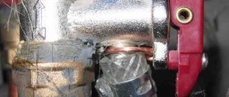
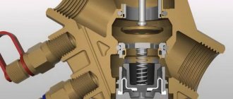
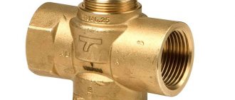
The section clearly shows the nut that tightens the seal ring.
How to choose
When choosing a three-way valve, you need to consider several parameters. It is good to enlist the help of an experienced plumbing engineer during the selection process.
First of all, you need to evaluate the purpose of the device - separation or mixing. The next step is to determine the installation location on the system diagram, as well as how to control the device. If you are planning automated heating control, you need to decide how this faucet will be controlled - by electric drive, thermostat or manually.
The following technical characteristics are subject to further analysis:
- Highway capacity. This is the volume of liquid passing per unit of time. The capacity of the crane must be no less. Too little clearance will create unwanted flow resistance and impede the operation of the entire system.
- Maximum and working pressure. It must also correspond to the calculated values for the heating system.
- Connecting dimensions. If an exact match of diameters cannot be achieved, then adapter fittings are used.
- Operating temperature adjustment range.
Guided by the listed parameters, you need to select from dozens of market offers several models that meet the specified requirements.
At this stage, it is time to compare price, warranty period, service availability and, of course, the reputation of the manufacturer. Guaranteed quality is provided by such market leaders as:
- Honeywell. The American company has been manufacturing, supplying, installing and servicing a wide range of components and entire heating, ventilation, and security control systems for the second century.
- Esbe. The Swedish company has also been supplying precise and highly reliable valves, fittings and system components for over 100 years, specializing in heating technology. The Scandinavian tradition of meticulous, high-quality workmanship is combined with innovative approaches to design.
- Valtec. The Russian-Italian enterprise successfully combines high Italian quality with a seven-year guarantee and affordable prices. Completely localized production with a European quality control system appeared on the market not long ago, but has already gained popularity.
There are also many suppliers on the market who have not managed to achieve such an impeccable reputation. Saving on the cost of the valve can later lead to its unstable operation, increased costs, or even failure of the entire system.
Selecting a three-way valve
Main parameters important when choosing:
- Nominal diameter.
- Bandwidth.
- Connection type.
- Control.
Nominal diameter
This is an indicator indicating the average internal diameter of pipes corresponding to several external diameters of the pipeline. The true internal diameter of the pipe in most cases does not coincide with the conditional one, but is as close as possible to it.
The outer diameter of a steel pipe corresponds to a certain nominal diameter. For example, for a steel pipe Ø 26.8 mm, a tap with a DN of 20 mm is required.
Bandwidth
Information about the throughput of the heating system is indicated in the technical documentation for the heating boiler.
Taking this data into account, you can select a crane.
If the throughput of the device is less than necessary, this will lead to increased pressure, increased load and rapid wear of the mechanism.
Connection type
The connection with which the locking mechanism is fixed to the pipe can be:
- Flanged - installed on the pipeline system using a special bolted connection. Tightness is ensured by rubber or steel rings.
- Coupled - connected to the pipeline using couplings with internal threads. Tightness is ensured with fluoroplastic tape, mastic or sealant.
- Fitting - the ends of the locking mechanism have an external thread, fastening is carried out using a nipple and a union nut.
Control
It is preferable to opt for a device equipped with a servo drive, which can be of three types:
- Open - in the absence of voltage, the coolant passes through an open channel.
- Closed - the coolant passes through the channel only when voltage is present.
- Universal - the device can operate in any of two positions.
The type of device you choose depends on the position it is in most of the time. Thus, for cold regions of the country, an open type servo drive is recommended, and for warm regions, a closed type.
Purpose and areas of use
A three-way valve is designed to divide the incoming flow into two outgoing ones, with the ability to turn off any or even all outputs. Essentially, this is a tee, but with the ability to switch and disconnect.
This design is used to organize heating systems and other pipelines where it is necessary to divide the flow of working fluid (gas) into several pipelines. The difference lies in the design, technical and operational qualities.
Connecting pressure gauges and other measuring instruments
Initially, three-way valves were used to install measuring, control devices and protection sensors. Most often - pressure gauges and manometric type.
It is useful to check pressure gauges that are constantly on and showing constant pressure by releasing the pressure and connecting the pressure gauge to atmosphere. This procedure is called a “zero” check.
To check the working pressure gauge with a control pressure gauge on site, it is necessary to simultaneously connect two devices at once.
All these and other functions can be performed by a three-way valve in various systems: heating, water supply, gas supply and engineering technological networks.
It is useful to check pressure gauges that are constantly on and showing constant pressure by releasing the pressure and connecting the pressure gauge to atmosphere. This procedure is called a “zero” check.
All these and other functions can be performed by a three-way valve in various systems: heating, water supply, gas supply and engineering technological networks.
Important: to check the working pressure gauge with a control pressure gauge on site, two devices must be connected simultaneously.
Connecting heating devices
These useful functions of the 3-way valve came in handy when connecting heating appliances to a heating system, with a bypass between the supply inlet and the return outlet from the radiator. In this case, devices with a rotation angle of 90 degrees and two positions are used:
- the coolant passes through the bypass and radiator;
- The coolant passes only through the bypass.
Standard scheme for using a three-way valve for heating with the principle of operation: radiator and bypass
The use of a three-way device with the ability to rotate 90 and 180 degrees in individual heating, with a single-pipe system (“Leningradka”), allows you to choose from three options:
- direct all the coolant through the radiator;
- direct the coolant through the radiator and bypass to other radiators;
- turn off the radiator and direct all the coolant through the bypass to other radiators.
These radiator connection options allow you to manually distribute the coolant flow, achieving more comfortable heating of rooms. For example, a room on the south side receives enough heat from the sun and the battery in it, in spring or autumn, can be turned off. And in winter, connect it together with a bypass. And in a room with windows facing north, in winter, all the coolant is directed through the radiator to heat the room, and in the autumn-spring period, part of the coolant is directed through the bypass, bypassing the radiator, to reduce the intensity of heating the room.
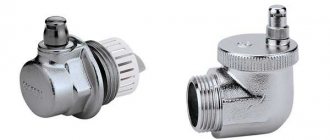
Air valve for heating to bleed air from the battery In modern heating systems, a special device is provided to remove accumulated air - an air valve for heating. Without this device, the heating would not be able to work properly.
Attention: the use of such a scheme in heating a multi-storey building with vertical risers is unacceptable. If you close the bypass and direct all the coolant through the radiator, then the remaining consumers will not receive a sufficient amount of heat.
Connecting temporary heat consumers
A three-way tap is convenient for connecting another consumer from the nearest point in the heating system. Especially if it is required temporarily. For example, for heating a winter greenhouse, garage, bathhouse or greenhouse. At the same time, in order to save money, you can do without a manifold-distributor, separate pipe laying and installation of additional valves.
Areas of application
Modern valves are in wide demand and are actively used in various areas of human activity. They are often installed in modern heating mains, which require constant adjustment of proportions when mixing different coolant flows. For such purposes, it is customary to use electromagnetic devices or models with a thermal head.
As for domestic use, in this case it is enough to purchase a thermostatic mixing device that will allow you to regulate the temperature of the coolant. It is supplied both to the underfloor heating piping system and to heating radiators. And if the household device is equipped with automatic control, then changing the temperature in the room will be much easier.
The use of a three-way valve in a heating system is profitable and economical
It should be noted that using a tee in a heating system to balance possible temperature surges is not only beneficial, but also economical. The device allows you to reduce the volume of fuel consumed several times, while the final efficiency indicators of the system will increase noticeably. In some rooms, the presence of such a device is simply necessary. For example, if a heated floor is installed in the house, then the device will prevent excessive heating of the floor covering.
Expert advice
When screwing the thermostatic head onto the body, do not use a plumber's wrench. The plastic housing of the thermostat can be crushed. You need to twist it by hand. The tightening force does not play an important role here.
The temperature sensor on the pipeline should be located as far as possible from the mixing point so that the flows have time to mix and equalize in temperature. From 0.5 meters on pipes up to 40 mm and up to 1.0 - 1.5 meters on pipes over 50 mm. The indoor air temperature sensor should be installed at a height of 1 – 1.5 meters. The floor temperature sensor is installed on the floor surface, or under the top layer of floor finishing, but no closer than 25 - 35 cm from the heating pipeline.
Automatic valves
By default, a three-way valve is controlled manually, using a stem outlet on one side of the valve with a rotary handle or nut. However, it is not always convenient to use this option.
The process of adjusting the circuit power using a three-way valve is not linear and depends on the return temperature, supply line and heat transfer power. To put it simply, manual control determines exclusively the proportion in which water from different lines is mixed; the temperature in the final section can change for quite a long time and not always evenly.
The valve can be effectively controlled automatically using servos or special hydrodynamic and pneumatic thermostat heads that can quickly and continuously change the setting of the three-way valve depending on the outlet temperature.
Electrically driven
A servo drive is a direct analogy to manual control, only the signal to action is given not by a person directly, but by an electronic control unit. This is an engine capable of turning a rod and changing its position depending on the incoming control signal.
Almost any manually operated three-way valve can be equipped with a servo drive, but it is better to use special designs that are compact in size and optimized for installing an electric drive.
The control unit is guided by the temperature readings at the valve outlet in the target circuit or by the flow and return temperatures to calculate the optimal setting.
As soon as the desired value is received, a control signal arrives at the servo drive, and it changes the position of the rod or the rotation of the ball inside the valve. Naturally, without an electronic control unit, using servos is simply pointless.
The advantage of servo drives is the ability to automate the operation of the heating system as much as possible. When you turn on automation in the Smart Home system, you can even set heating parameters from your mobile gadget.
With thermostat
The automatic regulation of a three-way valve can only be entrusted to a pneumatic or hydrodynamic thermostat. This is a mechanical control method. A thermal head is used, filled with a liquid or gas that reacts strongly to changes in ambient temperature. The main reaction is a change in volume.
The thermal head is connected through a channel to a piston and a movable valve of a three-way valve. When the volume of the heat-sensitive medium changes, the installation of the valve also changes.
Three-way valves with thermostats require careful pre-setting
After installation, it is important to determine the temperature limits at the measurement point and assign the extreme positions of the tap to them, thereby determining the adjustment range
Setting the target temperature of a circuit with radiators or a heated floor is done manually by adjusting the pressure in the thermal head. Further, when the current heating value changes, the proportion for mixing hot water and return water in the three-way tap is automatically adjusted.
Three-way taps with a thermostat are in demand where it is necessary to reduce the energy dependence of heating or reduce the overall cost of installation, since they are cheaper than devices with servo drives and do not require an expensive controller for their operation.
Electrically adjustable models
A three-way valve with an electric drive allows you to control the flow of coolant in the heating system of a private home as efficiently as possible. Unlike its manual counterpart, when the user independently sets the immersion level of the control rod in the mixer, this option is equipped with a special electric motor - a servo drive. Compared to a standard motor, the shaft in it does not rotate around its axis, but rotates at a given angle at the command of the controller.
Today on the market of specialized devices you can find two types of 3-way valves with a drive:
- Fully equipped.
- Only with drive and sensor.
Models of the first type are equipped not only with an electric motor, but also with a temperature sensor and controller. The latter are equipped only with a motor and a heating sensor. They will require a separate purchase of a control module. The task of this block is to analyze the signal coming from the temperature sensor, process it and perform the appropriate action.
Electric valve Source armastock.ru
For example, when the heating level drops, the sensor sends a signal to heat up. Having received the information message, the controller sends a command to the drive to rotate the rod accordingly in order to open the valve to allow the hot flow to pass from the pipe into the system.
Note! The electric drive model allows you to quite accurately set the parameters for adjusting the heating system and link events to time or even to smart control. However, a conventional three-way thermostatic valve is more stable, does not require a power source for operation, is inexpensive and allows you to control the temperature according to a strictly specified value.
Principle of operation
The three-way valve is equipped with three pipes for connecting lines. A valve is installed between them to regulate the water supply to two of the three branches. Depending on the orientation of the tap and its connection, it performs two functions:
- mixing two coolant flows into one outlet;
- division from one line to two outputs.
A three-way valve, like a four-way valve, does not shut off the channels connected to it, but only redirects the liquid from the inlet to one of the outlets. Only one of the exits can be closed at a time, or both can be partially blocked.
In the simplest version, radiators are directly connected to the boiler, in series or in parallel. It is impossible to adjust each radiator separately according to thermal power; it is only permissible to regulate the temperature of the coolant in the boiler.
In order to still regulate each battery separately, you can insert a bypass parallel to the radiator and after it a needle-type regulating valve, with which you can control the amount of coolant passing through it.
A bypass is needed to maintain the overall resistance of the entire system, so as not to disrupt the operation of the circulation pump. However, this approach is very expensive to implement and difficult to operate.
The three-way valve actually combines the connection point for the bypass and control valves, making the connection compact and easy to operate. In addition, due to smooth adjustment it is easier to achieve the target temperature in a limited circuit containing one or two radiators in a specific room.
If you limit part of the coolant current from the boiler and supplement it with return water returning from the radiator to the boiler, the heating temperature decreases. At the same time, the boiler continues to operate in the same mode, maintaining the set water heating; the water circulation speed in it does not decrease, but fuel consumption decreases.
If one circulation pump is used for the entire heating system, then it is located on the side of the boiler in relation to the inclusion of the three-way valve. It is installed at the return inlet of the boiler, through which already cooled water from the radiators flows, acting as a flow separator.
Hot coolant from the boiler is supplied to it at the inlet; depending on the valve setting, the flow is divided into two parts. Some of the water goes to the radiator, and some is immediately discharged in the reverse direction. When maximum thermal power is needed, the valve is moved to its extreme position, in which the inlet and outlet leading to the radiators are connected.
If heating is not needed, then the entire volume of coolant flows through the bypass into the return line, the boiler only works to maintain the temperature in the absence of real heat transfer
The disadvantage of such a connection is that it is difficult to balance the heating so that the same amount of coolant flows into each branch and to each radiator; in addition, when connected in series, the water that has already cooled down reaches the outer radiators.
In multi-circuit systems, the easiest way to solve the problem of uneven heat distribution is to use a collector group with circulation pumps on each individual circuit
This is especially important in houses with two or more floors and a large number of radiators or with heated floors
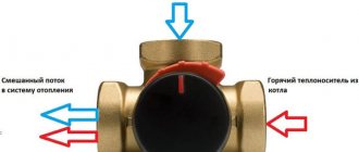
The three-way valve works to mix the two flows. The line from the boiler is connected through one input, and the return pipe through the second. Mixing, the water flows to the outlet connected to the heat exchanger.
This connection diagram is especially relevant when connecting a heated floor.
It makes it possible to limit the maximum water temperature in the circuit, which is especially important, given the maximum permissible value of 35ºC at a coolant temperature from the boiler of 60ºC and above
Water circulation in the underfloor heating pipes is constantly maintained, which is necessary for uniform heating without distortions. In fact, hot water from the boiler is supplied only to heat the cooling coolant in the heated floor circuit, and the excess is discharged back to the boiler.
Thus, even in high-temperature heating, where the boiler heats water to 75-90ºС, it is possible to install heated floors with heating at 28-31ºС.
DIY valve installation
We present to your attention several schemes for installing a mixing valve.
A scheme that is used mainly in boiler rooms of heating systems that are connected to a hydraulic separator or to a free-flow collector. The pump, which is located in the second circuit, ensures the necessary circulation of the coolant.
Attention! In the case when the valve is planned to be directly connected to the coolant source on the bypass, which is connected to port B, then it will be necessary to install a valve with hydraulic resistance, which will be equivalent to the same resistance of this source.
If this is not done, then the coolant flow in the segment A-B will fluctuate depending on the movement of the rod. It is worth noting that this installation scheme provides for a possible interruption of coolant circulation through the source if the installation is made without a circulation pump or hydraulic separator in the main circuit.
It is not recommended to connect the valve to a pressure manifold or heating networks in the absence of devices that can throttle excess pressure. Otherwise, the coolant flow will fluctuate seriously.
If the return is overheated, it is allowed to get rid of excess pressure using a jumper, which is mounted parallel to the valve mixture in the circuit.
Carrying out quantitative adjustment by changing fluid flow rates is the main function performed by this three-way thermal valve. It is used where it is possible to bypass liquid to the “return”, but stopping circulation, on the contrary, is extremely undesirable. We also present a diagram for installing a three-way separating valve:
Important! A similar connection scheme has become quite popular in water and air heating units connected from individual boiler houses.
In order to link hydraulic circuits, it is necessary that the consumer's pressure losses be equal to the losses on the valve - balancer in the bypass. The diagram shown here should be used for installation on those pipelines in which there is excessive pressure. The movement of liquid is carried out due to strong pressure, which is formed using a circulation pump.
Rules for installation and operation of the crane
Before you begin installing the unit, you must become familiar with the installation and operating conditions set out in the technical documentation and on the labeling.
When installing three-way structures, it is important to determine the position of the outlet and inlet pipes in accordance with the directions of flows in the system. The arrows printed on the body of the product can help with this.
During operation, it is necessary to inspect the device for leaks and wear. Cork valves are regularly lubricated and the condition of their sealing elements is checked.
Required tools and materials
To mount the device into the system, you need to prepare:
- set of wrenches;
- pipeline tapping tool;
- tap;
- fum tape or tow.
Work progress
- Determine the installation location of the device.
- If necessary, cut out a section of the pipeline.
- For the coupling connection, prepare the required threads at the pipe ends.
- Wrap tape or linen winding.
- Screw on the pipes one by one and attach a pipe, device or drainage device to the third hole.
Features of installation and operation
To properly install a three-way valve, you should know several features:
- Refer to the diagram of arrows shown on the body. They indicate in which direction the water flow is moving.
- When welding during installation, do not allow the temperature flow at the joints to exceed 100 degrees. Make sure that no dirt or scale gets inside the device when welding.
- Choose a place for installation that can be easily reached if necessary.
- If the faucet operates with low-quality coolant, additional filters will need to be installed.
- The product can be screwed either vertically or horizontally - this will not affect its performance.
- In a heating system, the valve is installed before the circulation pump.
The operation of the device must be observed in accordance with the rules established in the instructions. And all parts require periodic inspection and maintenance.
Proper and correct use of the device will extend its service life and will serve properly.
Simplified mixing elements with temperature lock
An autonomous three-way valve of a simplified type can be installed in simple heating systems of country houses, where heat is obtained from a TT boiler. To function, it does not require a thermal head with a temperature sensor, and there is no rod there.
The thermostatic element, which is installed inside the housing, is adjusted to a certain temperature of the coolant at the outlet, for example. 50 or 60 °C (must be marked on the body).
The mixing valve of this sample always maintains the set temperature of the coolant at the outlet; this setting does not change. This gives rise to positive and negative aspects when using such fittings:
- advantage - cheaper, unlike a unit with a thermal head. The difference is about 30%;
- disadvantage - there is no possibility of adjusting the heating of the exiting coolant. If the factory settings are set to 55°C, then it will constantly supply water at this temperature ±2°C;
- Before purchasing a valve of a simplified design, carefully study the documentation for the solid fuel boiler; it usually indicates the minimum return temperature.
A thermostatic three-way valve is a rather useful thing in the heating system of a private home, which makes it possible to efficiently use the heated liquid, and thereby save fuel. Moreover, this part allows you to increase the service life of solid fuel boilers, and also plays the role of a safety element. On the other hand, you should not sculpt the valve just anywhere; it is always better to consult with a specialist who is well versed in this.
Operating principle and design of a three-way valve for heating systems
The design of a three-way valve is based on a conventional T-shaped tee. Two inlet pipes (in the diagram on the right and above) serve to supply cold and hot water. The outlet pipe (in the diagram on the left) removes the mixed flow. In the central chamber, the regulating sector rotates on an axis, partially blocking the incoming pipes. The figure shows how a sector three-way valve works
Figure 2. Operating principle of a sector valve
The overlap can be from 0 to 100%. The peculiarity of the design is that the more the lumen opens for one of the incoming pipes, the smaller the lumen becomes for the other. If the sector is in the middle position, 50% of each flow is passed through. By shifting the sector, for example, to the upper pipe, you can get the cold/hot proportions:
- 45/55%;
- 40/60%;
- 20/80%.
And so on until cold water is completely shut off (0/100%), in which case only hot water will flow into the outlet pipe
The valve can be controlled manually or using a bimetallic thermostatic device.
Figure 3. Diagram of operation of a thermostatically controlled valve.
This function can be performed using two two-way valves and a conventional tee used together. This is exactly what happens in two-valve mixers. To ensure constant pressure and accurately control the proportion of mixing of hot and cold flow, it is necessary to ensure that two taps open in antiphase (one opens, the other closes proportionally), for example, by placing them on a single axis.
Kinds
Three-way valves are divided into two large groups. They can be:
- Separating. They serve to proportionally divide the incoming flow into two outgoing ones.
- Mixing. Designed to mix two incoming streams into one summing
Figure 4. Diagram of operation of a mixing and separating three-way valve.
From the diagram it can be seen that the design of the mixing and separating valve is almost identical. They differ only in the directions of the flows. If installed correctly, the mixing valve will also work as a separating valve. You just need to configure the control system correctly. In case of manual control there will be no problems. It will be more difficult, but also possible, to configure electronic control. But the thermostatic control module, if connected via a separation circuit, will distribute flows depending on the temperature of the incoming flow. This will have to be taken into account when designing the heating system.
How many positions a sector valve with an electric drive has is shown in Fig. 5
Figure 5. Options for using an electric crane
In addition to sector three-way valves, saddle valves are also produced. Their operating principle is the same, but there are design differences.
Figure 6. Saddle or ball type valve
The mixing seat valve has a spherical working body moving on a rod; it locks the seats in turn, through which mixed flows pass into the chamber and then into the outlet pipe. The separating valve is equipped with two working bodies, mounted on a single rod and blocking the outlet flows. The more one is blocked, the more the other is open. Seat valves cannot be interchanged.
In addition, three-way devices are divided according to the control method:
Electrical. The sector is rotated using an electric motor with a gearbox. Such devices are connected to a computerized control system that reads temperature sensors and controls the flow in accordance with the built-in algorithm.
Figure 7. Electric crane
*
- Manual. They are used in simple circuits with a constant proportion of distribution or mixing of flows. The angle of rotation of the sector is set manually by turning the flywheel.
Figure 8. Manual control
- Thermostatic. Control is carried out by an autonomous thermostat. It is set to a certain temperature when setting up the system, and then it independently maintains it by passing part of the incoming flow from the radiator through the bypass pipe.
Figure 9. Esbe three-way valve with thermostatic control
If necessary, you can change the set temperature by turning the handwheel. It is often installed at the inlet of heating radiators to adjust the comfortable temperature in each room.
What is a three way valve?
The mechanism is otherwise called a tee. Its main tasks:
- Mix different water flows in the hot water supply system, heating lines, and so on. In simple terms, the system works like a mixing valve in a kitchen. The difference between the faucet is that it discharges water not into the sink, but into the pipeline.
- Divide the flow of water into different branches and distribute in directions.
Three-way valve device
The shape of the standard design resembles the letter T, so builders also call it a tee tap. It includes the following main elements:
- Sealed housing. It protects the entire system from moisture and negative environmental conditions.
- A valve having several passage channels.
- Several holes - inlet and for cold and hot water.
Operating principle of a three-way valve
To become familiar with how to operate the system, you need to study the instructions and find out the diagrams of the three-way valve. The main coolant in the system is hot water, and the cold liquid is waste material. There is a valve between the holes responsible for supplying hot and cold water. Depending on its position and installation method, there are several ways how a three-way valve works:
- mixes two streams into one;
- splits one stream into two lines.
It is a mistake to believe that the tee shuts off the taps connected to it. The main task of the mechanism is to redistribute the liquid and not be responsible for blocking its flow. In simple systems, the radiator is connected to the boiler in two ways: simple and parallel. The elements are adjusted simultaneously, otherwise it will only be possible to adjust the temperature in the boiler tank.
Tee device
A tee valve consists of tubes hermetically connected together that distribute the flow of liquid. These tubes are arranged in a T shape.
Parts that make up the device:
- metal case;
- a gate with transition channels of different shapes: in the form of a cylinder, cone or ball;
- pipes (3 holes: inlet, hole for cold water and for hot water).
Technical characteristics and scope of use depend on the material from which the part is made:
| Brass | A reliable and practical control device that is distinguished by long-lasting use. |
| Steel | It is quite comparable in reliability to brass, but the service life of steel taps is slightly shorter. |
| Cast iron | Used for industrial heating systems where pipes have a diameter of more than 40 mm. Not used in domestic heating pipelines. |
The device differs in the method of connection: it can be threaded, welded or pinned, connected using flanges and couplings.
Depending on the type of valve, the valve can have a gland or tension mechanism.
Installation recommendations
Although the process of installing a unit into a heating system may seem simple, there are several nuances that are worth being aware of. Before starting installation work, you should carefully study the instructions, which will allow you to avoid a large number of problems. First of all, this concerns the correct location of the device. On its body there are arrows indicating the direction of movement of the coolant. The device must be installed in accordance with these instructions.
Also, you cannot mount the device with the thermal head or the drive down. Before proceeding with installation, you need to turn off the coolant supply and check the pipeline for the presence of residual water. An equally important point is the choice of installation location, because the device must be freely accessible.
There are several installation schemes, and their choice depends on the method of connecting the heating system. If the operating conditions of the heat generator allow overheating of the return, then the appearance of excess pressure cannot be avoided. In such a situation, it is necessary to install a jumper that will throttle the excessive coolant pressure. It is mounted parallel to the valve.
If the device is connected directly to the heat generator, then a balancing valve must be installed. It is this diagram for connecting a three-way valve in a heating system that is most often used in autonomous heating systems. It should be remembered that it cannot guarantee the absence of circulation of the heat-carrying fluid through the source. To solve this problem, it is worth connecting a circulation pump and a hydraulic delimiter to its circuit.
If the temperature of the heat generator is higher than what is required by the consumer, a separating valve is installed in the system. As a result, a constant coolant flow is achieved in the boiler and consumer circuits, but the latter does not receive overheated coolant. To operate such a scheme, a pumping unit will be required.
Thus, we can give several installation recommendations:
- When installing any valve, pressure gauges must be installed before and after the product.
- To prevent various impurities from entering the device, you need to place a filter in front of it.
- The valve body must not be subjected to any stress.
- To improve the regulation process, a throttling device can be installed in front of the product.
Using the device allows you to rationally use the coolant, thereby ensuring energy savings. In addition, the product can increase the safety of the heat generator. But before purchasing a valve, you should make sure that its installation is appropriate.
Video description
The video shows a diagram of how the regulator works with a solid fuel boiler:
- The arrow on the body and the direction of the coolant in the system must coincide when installing the device.
- The correct installation is also determined by the designations on the device body - straight, perpendicular, bypass or combined stroke.
- Coolant distribution diagram.
It can be T-shaped or symmetrical, as well as L-shaped or asymmetrical.
Before the 3-way regulator is connected, the heating system must be switched off and the coolant pipe must be de-energized. In addition, it is important that there is no sediment inside the pipes. Otherwise, the device will quickly clog and deteriorate.
Important! It is necessary to install the thermal control valve on a section of the heating pipeline with open free space and easy access. In this case, the thermal head or drive after installation should not be located at the bottom of the housing. Since in the future, with the slightest leak, they will quickly deteriorate.
Types of taps
Classification of the product according to various criteria:
Depending on the valve, they are distinguished: Regulating. It is equipped with an electromechanical device that opens the necessary valves. It also includes a rod with manual or automatic adjustment
Important! The rod cannot be knocked out even with the strongest water pressure, since it is located inside the device.
Constipated. It includes a ball device that switches the flow of water.
The peculiarity of this device is that it is installed on low pressure systems. It is very simple in design, requires constant maintenance and wears out quickly.
According to product material:
- Brass is the most popular material due to its long service life, small size and low weight.
- Carbon steel is an excellent alternative to brass.
- Cast iron - used for large diameter pipes (40 mm and more). It is not practical for private houses.
- Bronze is a material with a long service life.
Depending on the installation method:
- coupling;
- flanged;
- pin;
- for welding;
- fitting-end.
For the heating system, the following types are used: With constant hydraulic mode - adjusted in accordance with quality indicators. It is suitable for consumers with high-quality coolants of a certain volume.
With variable hydraulic mode – adjustable according to the required amount of water. It is more suitable for those for whom quantity matters.
From the device flow path option:
- trial run;
- full bore.
From the type of built-in shutter:
- conical;
- cylindrical;
- ball.
Based on the shape of the plug valve, the following types are distinguished:
- T-shaped;
- L-shaped;
- S-shaped.
From the mechanics of the bolt element:
- Stuffing box – controls the adjustment of the water jet from above the fittings due to the stuffing box;
- Tensioners - controls the adjustment of the water jet from below the fittings due to the nut.
Depending on the heating of the case:
- with heating;
- without heating.
Depending on the technical parameters, the following valves are distinguished:
- T-shaped – the adjustment knob can be in 4 positions;
- L-shaped - the adjustment knob has two modes, including a rotation angle of 180 degrees.
From the device control mechanism:
- Manual – connects water flows in approximate proportions, cheap, looks like a standard ball valve;
- Electric drive - for operation, additional equipment is used - a motor or a magnetic method, there is a possibility of getting a shock from the current;
- Pneumatic drive is the most optimal option for use.
Important! With an electric drive, you can easily balance the heat so that the temperature level in the rooms farthest from the boiler is the same as in those close to it.
Execution options
How can a three-way valve be installed under a device to determine a pressure value of 1:2 inches? Here are a couple of descriptions of the most popular designs.
Cork tensioner
The three-way cork valve with tension seal 11b18bk is produced in the following configurations:
- Two pipe (DN 15) or metric (M20x1.5) threads and a drainage hole.
Valve version with drain hole.
- One pipe thread and one metric thread plus drain hole.
- The same, but with a handle (lever or butterfly).
- Two threads (DN 15, M20x1.5 or a combination thereof) and a flange for connecting a control device to determine the pressure value.
The valve is very simple in design, but has a couple of significant disadvantages:
- Quite a significant switching force (distinctive, however, for all plug valves).
- There is a constant risk of tearing off the plug shank when tightening the nut. Brass is a fairly soft metal and excessive force
.
The operating principle of the three-way valve for the pressure tester is simple and straightforward: a T-shaped cutout in the rotating plug is connected to one or two outlets when it is turned. Based on this, the following combinations are available in different positions:
- The outlet is plugged, the device for determining the pressure value is connected to the atmosphere through a drainage outlet or a flange.
- Pressure is applied to the control valve when the drain or flange is closed.
- The outlet operates for discharge when the pressure gauge is closed.
Ball with drainage
For the sample, we will consider a three-way ball valve for a device for determining the pressure value 11B27p. It is interesting due to the implementation of drainage. In essence, this is an ordinary sleeve valve with a long body and a drainage hole.
on one side of the check ball.
Faucet 11B27p with drainage and plug screw.
Here are the properties of the product.
Parameter Value Maximum operating pressure 16 atmospheres Maximum operating temperature For water - 140C, for steam - 225C Material of body and shut-off ball Brass Material of rod seal and seats Fluoroplastic Drainage Hole in the body with a plug screw Wholesale cost 180 rubles
Choice
To choose the right valve, you need to take into account many different nuances.
First of all:
- number of circuits in the heating system;
- design feature of valve control;
- inlet pipe diameter;
- throughput of heating system pipelines;
- the material from which the valve is made.
It’s easy to figure out the number of heating system circuits yourself. With other moments of choice, everything is much more complicated. To find out how a three-way valve works and works, just delve into this issue. And in order to correctly determine even its dimensions, it is necessary to have a concept in thermodynamics.
Advice from the editor: it is better to entrust such a complex issue as choosing a valve to a specialist. The performance of the heating system will depend on the correct choice.
With an automated control drive, it is able to distribute hot water flows in the desired direction and in the required quantity.
Valves are not able to cope with such a task, which indicates the need for a three-way valve in the heating system. Using a valve in the system, there is no need to come up with some kind of remote control panel to control it. Everything is done without human intervention.
Watch the video in which an experienced user explains in detail the operating principle and design of a three-way valve for a heating system:
general information
It is no secret that the problem of uneven heat distribution in a room often causes a lot of trouble for owners. To get rid of this unpleasant phenomenon and create a comfortable temperature regime, you need to introduce a special device into the heating system - a thermal power regulator or a three-way valve.
The mechanism ensures recirculation of the coolant fluid by mixing a certain amount of cooled treatment with the main current. Currently, tees are installed in hot water supply systems, heating circuits and plumbing systems.
Three-way valve – multifunctional, durable
In most cases, three-way valves are installed in heating systems with many components and circuits, which is necessary to stabilize the temperature in all radiators. The use of the device allows you to control the flow of coolant, distributing it to different parts of the room (for example, in the kitchen, garage and living rooms). Among the main advantages of the invention are:
- compact and ergonomic dimensions;
- multifunctionality;
- ease of installation, operation and maintenance;
- high tightness;
- long service life;
- ease of switching between operating modes.
In addition to the advantages, tees also have disadvantages. These include the likelihood of valve jamming if operating rules are not followed and rapid wear of inexpensive products.
This video will tell you how to install a three-way valve correctly:
Features of choice
When selecting a three-way valve for installation in a process pipeline, you must first determine its purpose. This is due to the fact that devices for mixing or separating media flows differ in operating principle and design features
In addition, you need to pay attention to the following parameters:
- conditional pass;
- throughput;
- type and characteristics of the actuator;
- operating and maximum permissible temperature and pressure indicators.
The main characteristics of the valves are indicated in the accompanying documentation and on the product body. Marking is carried out in accordance with the requirements of GOST 4666-2015 and provides for the following types:
- Molded on the front side of the body indicating the material, nominal diameter and pressure. The manufacturer's trademark must be on the reverse side.
- A plate attached to the surface of the housing indicates the scheme according to which the transported medium is supplied.
- The plate fixed on the lid must reflect the following information - the name of the manufacturer, marking according to the table of figures and serial number. In addition, indicate the nominal pressure and diameter, date of manufacture and mark of circulation on the market of countries belonging to the Customs Union.
The outer surfaces of the valves are painted in a color chosen in accordance with GOST or taking into account the wishes of wholesale buyers. Each type of material usually has its own color.