When it comes time to think about the heating system in your home, a lot of technical questions arise. Of course, you want to do everything correctly, thoroughly and inexpensively. But it’s not enough just to properly plan the system itself; you also need to take care of the water flowing in the veins of your home. Excessive water hardness and abrasive impurities in it can shorten the life of your system by decades. Today there are many ways to purify water. And you definitely shouldn’t skimp on them. Savings here will entail large expenses in the future, including replacement of machinery and equipment. When using water from a well or reservoir, several filters must be used to protect the coolant. There are four main and mandatory ones:
- ion exchange resin filter
- cascade mechanical cleaning filter
- universal filter mesh
- coarse filter
The uninitiated user, of course, will have natural questions. What are heating filters for, are they useful, do you need to use them all at once and at what stage? The questions are natural and require a detailed answer. It is worth planning the installation of filters at the design stage of your home. It is necessary to allocate space for them, taking into account installation and maintenance. Provide a connection system. If the moment was missed, the filters can be installed later, but this will entail additional labor costs. Therefore, if you are still at the planning stage, it’s time to study each filter in detail.
Mechanical cleaning filter, washing cascade
A flush filter for heating systems is necessary for the mechanical purification of water supplied to a heating system with a working environment temperature of up to one hundred and ten degrees. The filter purifies water from suspended matter, mud and silt deposits, sand, etc. The cascade filter is more compact than other filters with similar functionality. The volume reduction was achieved thanks to the latest nested filter system. Two filter elements of different sizes are placed one inside the other, and the vertically directed water is twisted into a spiral and is effectively cleaned of mechanical impurities. The device is installed strictly vertically. Cleaning the filter elements is quite simple; there is no need to remove the mesh inserts. The body and bulb are most often nickel-plated. Filter elements made of stainless steel. The filter does not take up much space. Simple and reliable in operation.
Mud collectors for heating systems: main types and their design
Any heating system, no matter whether central or completely autonomous, is a rather complex “organism” that includes many elements, each of which fulfills one purpose or another. And in this list of components there must be a place for filtration and coolant purification devices. This function is assumed by mud collectors.
Mud collectors for heating systems
When designing central heating systems, such filters are mandatory, both in boiler houses or at thermal stations, and on collectors and elevator units directly in buildings connected to heating networks. But in individual construction, no, no, and there are situations when inexperienced home owners do not fully understand how important mud collectors are for heating systems, and do not include them in a independently developed scheme. And it’s completely in vain - these very inexpensive, easy-to-install and maintain devices can significantly improve the operation of the entire system, significantly extend the trouble-free period of its operation, relieve owners from the rather labor-intensive and dirty work of periodically cleaning and flushing pipes and radiators, and significantly reduce operating costs for home heating.
Purpose of mud filters and advantages of their use
The carrier of thermal energy from the boiler or central line to the radiators is the coolant liquid. Most often, this role is played by water, pure or with some chemical additives. In certain conditions, for example, in private houses where the owners do not live all year round, special liquids that are resistant to negative temperatures are often used - antifreeze, but even in them water takes up a significant part of the total volume.
Water is always a very active oxidizing agent, causing corrosion of metal parts of heating pipes, in-house wiring, radiators, and shut-off and control valves. The resulting rust particles peel off from the walls over time and are picked up by the flow. However, if certain conditions are created in a pipe, on a tap, in a radiator, at a welded or threaded joint, in a tee or at a bend (narrow passage, unevenness, overflow from a weld, change in flow direction, etc.), then this the place with a high degree of probability becomes vulnerable to the formation of a plug - small particles of scale settle, accumulate, layer, narrowing, and sometimes completely blocking the passage of the coolant.
Many people are probably familiar with the situation when heating radiators heat up unevenly, not over their entire area. It also happens that several sections of the battery generally remain cold - the coolant clearly does not circulate through them.
Radiator sections clogged with dirt are the reason for their uneven heating
If the check shows that there is no air in the radiator, then such a picture can only be caused by the accumulation of dirt.
Sometimes when opening the battery you can see a similar “sad” picture
Such radiators will not be able to provide the required heat transfer, and you will have to resort to emergency measures - remove them and thoroughly wash them. And this, believe me, is a very complex and time-consuming process.
How are heating radiators flushed?
There are several technologies for cleaning pipes and radiators from accumulations of dirt and scale deposits. Details on how to flush the heating system , as well as ideas and testing it using the pressure test , are described in a special publication on our portal.
Not only radiators become overgrown with dirt - it also clogs pipe channels, taps, air valves, expansion tank pipes, etc. As a result, the operation of the heating system begins to completely go out of balance.
Clogged pipes are an additional, completely unnecessary load on the pump and boiler, unnecessary energy costs
Thus, narrowed passages do not provide the required volume of coolant circulation, and in order to achieve the desired temperature it is necessary to increase the current power of the boiler. Moreover, the layer of plaque on the walls of pipes and radiators becomes a “thermal insulating gasket”, that is, heat transfer is sharply reduced. And this is another reason for increasing heating costs.
This “migrating” dirt and solid particles can lead to additional load on the circulation pump, damage to its turbine and complete failure. Well, the saddest thing will be if blockages form in the boiler heat exchanger - this in most cases leads to burnout of the heat exchanger, often leading to the replacement of all expensive equipment as a whole.
An increased concentration of solid inclusions can seriously change the electrolytic characteristics of the coolant, which is extremely undesirable for heating systems operating from an electrode (ion) boiler.
Electrode boilers require special coolant properties
The operating principle of electrode boilers is fundamentally different from other heaters. More details about the design and characteristics of ion heating boilers can be found in a special publication on our portal.
Unfortunately, it is not possible to completely eliminate the formation of solid suspensions in the circuits and heat exchange devices of the heating system. This means that it is necessary to organize a “collection point” in which debris and dirt will be retained, filtered out of the liquid, and then regularly removed, using very accessible methods that do not require dismantling any components of the heating system. This is precisely the main function of mud filters.
Equipping the system with such filtering devices immediately provides a number of advantages:
- The most complex and expensive components of the system - the pump and the boiler - receive reliable protection from contamination, channel clogging and damage. Consequently, their service life increases significantly.
- There is no need to frequently drain the coolant to replace it with a new, clean one - it will already be maintained in a condition satisfactory for use. Considering that some coolants cost quite a lot, this is another significant saving.
- The use of filters and high-quality, correctly selected coolant will free owners for a long time from the procedure of cleaning and flushing all heating systems.
Much depends on the quality of the coolant
Of course, maximum efficiency and operational safety of a heating system can only be achieved by using high-quality coolant. A special publication on our portal is entirely devoted to the types and characteristics of coolants for heating systems .
- Heating radiators that are free from dirt and solid deposits provide maximum heat transfer, and free channels of pipes, fittings, connecting units and control valves provide minimal hydraulic resistance to the coolant. Both allow the boiler and pump to operate optimally with minimal consumption of the corresponding energy carriers. Moreover, it is estimated that in general the saving effect of operating a “clean” system, compared to one with mud deposits, can reach even 40%.
In a word, there is something to think about - installing a relatively inexpensive and easy-to-use device immediately gives owners a lot of preferences.
Main types of mud filters and their design
General classification of mechanical cleaning filters
Filters for rough mechanical purification of water from solid impurities (which deserve the name mud filters) use three basic principles for separating suspended matter:
A mud settling tank in which solid particles are separated due to gravitational forces
- Settling filters use gravitational forces - due to a sharp increase in volume and, accordingly, a drop in flow rate, solid particles settle to the bottom under the influence of gravity. Often this is complemented by a sharp change in the direction of movement - then turbulent and centrifugal forces are also included in the “work”, carrying more inert heavy particles to the periphery of the flow, where they settle, thereby releasing water.
A typical structure of such a mud trap is shown in the diagram below:
Scheme of operation of a settling filter with a change in the direction of coolant flows provided by the design
Usually this is a vertically located cylindrical body (item 1), into which two pipes with flange connections are welded: inlet (item 2) and outlet (item 3). The bottom of the body is closed with a flange plug (item 4), the top is welded tightly. The bottom plug usually has a pipe (item 5) for installing a tap to it for carrying out maintenance work - draining sludge and washing the filter. There is also a pipe on top (item 6) - a valve is installed here to release air when the system is filled with coolant.
In the cavity of the central cylinder there may be one or more jumpers (item 7) that sharply change the direction of the flow of water passing through the filter (shown by blue arrows). Solid inclusions (pos. settle down, where a layer of sludge is formed (pos. 9), which is regularly cleaned during preventive maintenance.
Such filters are usually installed on large pipelines, for example, in industrial plants. In a home heating system, their use is not very rational. However, the principle of gravitational water purification is successfully used in other filter models.
In mesh filters, the main element is a mesh with small cells
- Mesh filters - in them, the water flow is passed through a mesh structure with cells of a certain size. All particles whose diameter exceeds the mesh size remain in the filter.
Separation of suspended matter in such filters occurs due to the action of permanent magnets
- Magnetic filters, as the name suggests, contain permanent magnets that attract small particles of metal and metal scale. It is recognized that installing a magnetic filter, in addition, sharply reduces the likelihood of scale formation on the walls of pipes and in the heat exchangers of heating devices.
As already mentioned, very often in modern mud filters used for heating systems, two, and sometimes all three, principles of mechanical water purification are combined.
Depending on the type of installation in the system, mud filters can be of three different designs:
- On pipes of small and medium diameter, typical for autonomous heating systems, sleeve filters are often installed.
Filter with a coupling type of connection
On both sides of such a product for connection to pipes, couplings with internal (there are models with external) threads are provided. Accordingly, hexagons are provided on the filter housing for inserting an open-end, adjustable or gas wrench during installation or dismantling. Such filters are usually immediately “packed” into the system when it is assembled.
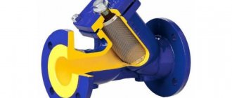
- It is extremely difficult to work with threaded connections on medium- and large-diameter pipes (over 2 inches), so filters with flange connections are most often installed in such areas.
Mud filter with flange connection
A flange connection involves installing an O-ring, and then tightening it with bolts. When initially installing such a filter, there are somewhat more concerns, since it is necessary to weld the counter flanges onto the pipe in a strictly established position while maintaining the installation length of the product. But if you need to remove the filter, this will be quite simple to do, without resorting to dismantling an entire section of wiring.
- There are filters that are mounted “tightly” to the pipes - such devices have pipes on both sides, along the edge of which there is a chamfer - for the weld.
There are models that are simply tightly welded into the pipeline.
Probably the only advantage of such filters is their lower cost. But in case of an accident or the need for replacement, you will have to cut out a section of the pipe.
Dirt filter specially designed for installation in polypropylene pipe circuit
Non-removable, welded mud traps also include filters in a polypropylene casing - specially designed for small-diameter pipes of similar design.
They are also welded immediately during installation of the pipework, and to replace them, if necessary, you will have to cut out an entire section. Therefore, they are probably not particularly popular - usually most craftsmen prefer to install metal couplings, and only then switch from them to polypropylene.
According to the method of maintenance, filters also have their own gradation:
- Self-flushing - in such mud tanks there is a tap in the lower part, when opened, the accumulated dirt (sludge) is washed out with a stream of water. At the same time, the filter mesh is cleaned.
Filters with self-cleaning capabilities
For better cleaning of the mesh, a bypass with a valve is often provided when installing the filter. This makes it possible to redirect the flow of water from the reverse side during maintenance - even solid inclusions tightly stuck in the cells are washed out very well and drained into the drain tap.
- Wash filters. They do not require dismantling the entire product - after disconnecting a section of the system from the coolant supply, it is enough to unscrew the plug or remove the flange plug, remove the filter element and clean and rinse it (if necessary, or in models with cartridge inserts, replace it with a new one). Then the filter is assembled in the reverse order - and it is ready for use again.
In the flushing device, for maintenance work you will need to remove the filter element
- There is also a category of non-washable mud filters. To service them, you have to completely dismantle the entire device from the system. Of course, this is very inconvenient, and such products are not in demand and are practically not installed in autonomous heating systems.
And finally, mechanical filtration devices can be divided into two categories according to the degree of purification of the liquid passing through them:
- Coarse filters, which, in principle, are called “mud filters,” have meshes capable of trapping solid inclusions larger than 300 microns (0.3 mm).
- Fine cleaning devices are designed to filter out suspended matter ranging in size from 5 to 300 microns. They are usually used in post-treatment systems for tap water for domestic and food needs. Such filters are not used in a heating system - such high cleaning is not required here, and the filter elements themselves will quickly become clogged and require replacement or washing.
Now let's look at the most common types of mud filters that are installed in heating systems.
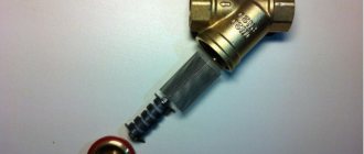
Brass mesh “oblique” filters
This is perhaps the most common category of mud filters used in local home heating systems. They have a coupling threaded connection in a fairly wide range of sizes - from ½ to 2 inches, which is quite sufficient for installation on any autonomous heating pipeline.
The design of the filter is quite simple:
The device of a brass “oblique” mud filter
The cast brass body (item 1) is a monolithic pairing of two cylinders, straight and inclined (item 3). On both sides of the straight cylinder there are threaded couplings for mounting the filter (item 2). The “oblique” cylinder ends with a brass plug (item 4) with a hex key. A sealing gasket is placed between the plug and the body, usually Teflon (item 5). In the most inclined part there is a filter element - a stainless steel mesh (item 6) with cells of a certain size.
An arrow on the housing must indicate the correct direction of flow of the filtered liquid. The beveled part always faces forward in the direction of flow.
The tables below present the main operational and installation parameters of brass “oblique” filters:
Main performance characteristics of brass “oblique” filters:
| Product parameters | Pipe diameter | |||||
| G½ | G¾ | G 1 | G 1¼ | G 1½ | G 2 | |
| Nominal pressure in the system, bar | 20 | 20 | 20 | 16 | 16 | 16 |
| Crimping pressure, bar | 30 | 30 | 30 | 24 | 24 | 24 |
| Mesh cell size, microns | 500 | 500 | 500 | 800 | 800 | 1000 |
| Distance between the centers of grid cells, mm | 1,1 | 1,1 | 1,1 | 1,4 | 1,4 | 1,6 |
| Density of mesh cells per 1 cm², pcs. | 156 | 156 | 156 | 83 | 83 | 59 |
| Maximum permissible coolant temperature, °C | +150 | |||||
| Degree of transparency (“transparency”) of the filter, % | 39 | 39 | 39 | 53 | 53 | 59 |
| Total filtration surface area with clean mesh, cm² | 17,9 | 32,6 | 44,8 | 55,7 | 77,1 | 111,0 |
| Average throughput of the device with a clean filter element, m³/hour | 3,15 | 5,0 | 9,9 | 15,5 | 24,0 | 28,5 |
| Nominal coolant flow with a clean filter, m³/hour | 1,41 | 2,24 | 4,43 | 6,93 | 10,7 | 12,7 |
| Average filter life | up to 30 years old | |||||
Installation characteristics of filters:
| Conditional bore, DN, mm | Pipe thread diameter | Construction dimensions | Empty weight, kg | |
| height H, mm | length L, mm | |||
| 15 | G½ | 40.5 | 51 | 0.132 |
| 20 | G¾ | 47.5 | 63.5 | 0.213 |
| 25 | G 1 | 53 | 68 | 0.285 |
| 32 | G 1¼ | 65 | 91.5 | 0.573 |
| 40 | G 1½ | 73 | 102.5 | 0.750 |
| 50 | G 2 | 88 | 126 | 1.160 |
Installation of such filters is not particularly difficult for those who are familiar with the basics of plumbing techniques. Typically, a shut-off valve is installed in front of the filter - it allows you to shut off the coolant supply to carry out preventive work to clean the device from accumulated dirt. But the main thing that is important to consider is the correct orientation of the filter in space:
| Correct installation | Incorrect installation | ||
| Correct installation on a horizontal area. The beveled cylinder is located at the bottom. | Quite often, would-be “masters” install the filter with the plug facing up, apparently for reasons that it is easier to get to it during maintenance. However, such placement leads to a very rapid contamination of the passage into the filter chamber with dirt, reducing the throughput of the device | ||
| Correct installation in a vertical area. The coolant flow is organized from top to bottom. | Such an arrangement in a vertical section with coolant flows upward does not allow filtered sludge to concentrate in the cleaning chamber for preventive maintenance. The cleaning capabilities of the device are sharply reduced, and dirt can accumulate on the walls of pipes or on shut-off valves. | ||
The filter is usually installed on the return pipe in front of the circulation pump or boiler, if the pump is structurally part of the boiler. Thus, all possible contaminants collected along the heating circuit are removed from the coolant, which has described the full circulation cycle.
Regular cleaning of the “oblique” filter is not particularly difficult. You just need to turn off the coolant supply taps on both sides (if a check valve is installed behind the filter along the flow of liquid, then you can only close it from the inlet side). Then a container is supplied from below to collect the leaking liquid and accumulated sludge. The plug is unscrewed with a wrench and the mesh is removed.
The mesh of the “oblique” mud collector, tightly clogged with sludge
The mesh should be cleaned with a polymer brush and then rinsed thoroughly with strong water pressure. The glass of the “oblique” cylinder itself is checked - there should also be no deposits left there. Then reassembly is performed by tightening the plug. At the same time, you can evaluate the condition of the sealing gasket, since over time it may require replacement.
Video: device and cleaning process of the “oblique” filter
You should be careful when purchasing such a filter. All the advantages mentioned in the table are valid only for high-quality brass products (some may have an external shiny nickel-plated or oxidized coating). Unfortunately, there are a lot of cheap fakes on the market made from silumin alloys, and no one can guarantee the long-term operation of such a filter.
Cast iron “oblique” magnetic filters
Externally, such filters are very similar to the brass filters discussed above and, in general, are similar to their design. The difference is in the material of manufacture: the body and plug are cast from cast iron. The filter element is the same cylindrical mesh made of stainless steel. The gasket between the plug and the body is usually paronite.
Cast iron “oblique” mud pan with a magnetic block
However, the filtering unit is supplemented with one more element. A stand is rigidly mounted along the axis of the plug, on which disk-shaped permanent magnets made of corrosion-resistant material are located at certain intervals. Thus, filtration takes place in two directions - the mesh catches mechanical impurities, and the magnetic block catches metal particles and scale. The quality of coolant cleaning only benefits from this.
Main characteristics of manufactured cast iron “oblique” magnetic filters:
| Conditional bore, DN, mm | Pipe thread diameter | Construction height, mm | Construction length, mm | Socket wrench size, S, mm | Metal mesh cell size, mm | ||
| N | H1 | L | L1 | ||||
| 25 | G 1 | 80 | 140 | 120 | 200 | 32 | 1.2x1.2 |
| 32 | G 1¼ | 100 | 155 | 140 | 220 | 46 | 1.4x1.4 |
| 40 | G 1½ | 110 | 180 | 160 | 280 | 46 | |
Please note that in the mounting dimensions columns two values of length and height are indicated. L and H are the usual installation values, and L1 and H1 - taking into account the mandatory leaving of the necessary space for free removal of the plug with stand and magnets during maintenance work.
Otherwise, the procedure for installing such filters in the system and the cleaning process do not differ from similar operations with “oblique” brass ones. In this case, the rack with magnetic disks is also cleaned and washed.
Flanged magnetic dirt filters
Such filters almost completely repeat the principle of operation of cast iron “oblique” filters - the only difference is in size. On pipes from G 2 and above, flanged devices are usually installed.
Flange magnetic dirt filter
Instead of a threaded plug, there is also a flange type plug. There is often a place for a drain hole, closed with a plug, which allows you to drain the sludge and flush it from time to time without having to remove the entire plug.
Characteristics of flange magnetic filters
| Conditional bore, DN, mm | Construction dimensions of products | Flange bolt hole diameter, d, mm | Number of bolt holes on the flange, n, pcs. | Mesh cell size, mm | |||
| height, mm | length, mm | ||||||
| N | H1 | L | L1 | ||||
| 50 | 140 | 200 | 230 | 280 | 18 | 4 | 1.4x1.4 |
| 65 | 165 | 250 | 290 | 355 | 18 | 4 | |
| 80 | 195 | 275 | 310 | 385 | 18 | 8 | |
| 100 | 215 | 315 | 350 | 425 | 18 | 8 | |
| 150 | 320 | 490 | 480 | 645 | 22 | 8 | 2x2 |
| 200 | 415 | 630 | 650 | 890 | 22 | 12 | |
When installing such filters, the installation length and height (L and H), and operational length (L1 and H1) are also taken into account - taking into account the place for removing the plug and removing the mesh and magnetic block.
Subscriber filters, mud-settlers
Among the most common filters installed on heating mains, in particular, in areas where they are connected to intra-house networks, are the so-called subscriber filters. They can be produced in vertical or horizontal versions, but vertical is much more common. Such devices combine the functions of a sump and mesh filtering of the liquid passed through them.
Such mud filters are called “subscriber filters.”
Such devices have a very long service life, are easy to maintain, and their large internal volume allows you to reduce the frequency of regular maintenance.
Approximate diagram of the subscriber filter-dirt filter
Structurally, they are a cylindrical body made of steel pipe (item 1). Nozzles with a flange are welded into it on both sides - inlet (item 2) and outlet (item 3). The nominal diameter of the nozzles corresponds to the pipe into which the filter fits.
The exhaust pipe has a special design. Its length reaches approximately the central axis of the cylindrical body, and is plugged from the inside. In the segment from the wall to the plug, holes with a diameter of 5 to 8 mm are drilled in its walls, so that their total area is no less than twice the cross-sectional area of the pipe. A filter mesh (item 3) with cells of the appropriate size is placed on top of these holes.
A flange is welded along the lower edge of the pipe body, to which the bottom plug is bolted (item 5). Typically, the plug provides the ability to install a drain valve (item 6) for regular cleaning of the cavity from accumulated dirt.
The filter cover is tightly welded, but it has a pipe or hole for mounting an air vent valve (item 7).
Characteristics of the line of vertical subscriber mud filters
| Conditional bore, DN, mm | Mounting dimensions | Empty weight, kg | |
| height H, mm | length L, mm | ||
| 40 | 217 | 308 | 16.7 |
| 50 | 240 | 359 | 22.7 |
| 65 | 369 | 419 | 45 |
| 80 | 369 | 419 | 48.9 |
| 100 | 421 | 473 | 70 |
| 125 | 421 | 473 | 73 |
| 150 | 563 | 526 | 103.3 |
| 200 | 669 | 626 | 184 |
| 250 | 785 | 730 | 269 |
The coolant, passing through such a filter, goes through two stages of cleaning. Large and medium-sized particles precipitate under the influence of gravitational and centrifugal forces, while smaller ones are already retained on the mesh.
Due to the simplicity and reliability of the design, relatively low production cost, and high operational potential, such subscriber filters are widely used in in-house wiring of heating systems. In particular, they are a mandatory element of the elevator unit.
What is an elevator unit of a heating system?
The temperature and operating pressure of the coolant coming from the heating mains must be brought to certain values that correspond to the capabilities and needs of a specific in-house heating system. One of the simplest and most reliable solutions is the installation of an elevator unit , the design and operating principle of which is described in a special publication on our portal.
Self-cleaning dirt filter with additional air vent function
And at the end of the publication - an overview of another type of filter. These are modern self-cleaning devices in a compact vertical housing that will not take up much space and will ensure high-quality cleaning of the coolant from impurities.
Moreover, some models are equipped with an additional option - they allow you to separate (separate) dissolved gases and automatically remove them, preventing the well-known “scourge” of any heating system – its “airing”, that is, the formation of air pockets.
One of these filters is shown in the diagram:
A modern dirt filter can also combine the function of an automatic air vent
Typically, the housing of such a filter is a metal cylinder (item 1), with a coupling connection to the inlet (item 2) and outlet (item 3) pipes. A glass (pos. 6) is screwed to the bottom for collecting sludge (pos. 7) - it can also be metal or plastic, including, on some models, transparent, which allows visual monitoring of the condition of the filter. At the bottom, the glass ends with a tap (position for cleaning and rinsing the device.
There are grids installed inside the central part of the body. One of them, the outer, larger one (item 4), acts as a separator of air and other gases dissolved in water. Bubbles accumulate and grow on it, which then, when they reach a certain size, independently rise upward under the influence of gravity.
An internal mesh with small cells (item 5) is used to filter solid particles from the coolant.
A block for collecting separated air (item 9) with an automatic air removal system is screwed onto the top of the housing. The valve design includes a float (item 10) connected by an actuator lever (item 11) to a needle valve (item 12). As air accumulates in the block, the float drops lower and lower, and when it reaches a certain level, it opens the needle valve through a lever. The air exits through the holes in the cover (item 13), the float rises again, and the valve closes.
The procedure for cleaning such filters from sludge has already been mentioned in the publication - just open the tap from below and wash out the dirt with a stream of water. It’s even better if it is possible to create a reverse flow of liquid for cleaning.
An example of a dirt filter with magnetic inserts, a self-flushing function, an automatic air vent and two pressure gauges
Some filters of this type are additionally equipped with magnetic inserts, which increases cleaning efficiency. In addition, many models have built-in pressure gauges that indicate the fluid pressure at the inlet and outlet of the filter. A simple comparison of the readings of these devices can give a very clear picture of the degree to which the filter elements are clogged with sludge (with a clean filter, the readings should be approximately equal), that is, signal the need for preventive maintenance.
Universal filter mesh
The simplest mesh filter for heating. It consists of a body (metal) and a cylindrical mesh located inside the flask. The housing is closed with a plug or tap, depending on the type of filter. Connection system - flange. There are washable and non-washable filters. Non-flush ones must be replaced at the end of their service life. The washers last a long time thanks to cleaning. It is necessary to stop the water circulation, dismantle the cover, remove and wash the mesh, and install it. In addition to its relatively low price, the mesh is attractive due to its simple design, easy maintenance and cheap components. This filter is installed in front of the fine cleaning system. This is the penultimate level of protection. Serves to purify water from scale or solid inclusions. Pipe fittings or pumps damaged by scale will cost tens of times more than a cheap filter. The filter does not take up much space.
Installation
Installation of the strainer must be carried out in accordance with the manufacturer's instructions, which should be read before installation. However, there are general installation recommendations that are suitable for most models:
Correct installation of the filter in vertical and horizontal positions.
- The filter must be installed in the correct direction (indicated by the arrow on the device body);
- For horizontal installation, the filter is mounted with the plug with the mesh down;
- If the device is mounted on a vertical pipeline, the coolant flow should move from top to bottom (the plug “looks” down). If the flow moves from bottom to top, a standard oblique filter will not perform its function. In this case, all solid contaminants will settle at the junction (corner) of the horizontal and vertical pipelines;
DN40, 1”/1/2.
Note! A universal mesh filter has been developed especially for heating systems in which there are sections of a vertical pipeline with coolant moving from bottom to top. For this filter, the compartment with the mesh is located at an angle of 105° relative to the direct flow, i.e. turned towards the flow. Thanks to this, solid contaminants are retained in the “dirt trap” compartment, and do not settle in the lower part of the pipeline. In addition, this design creates turbulence inside the compartment, which does not allow colloidal particles to accumulate on the mesh.
- After installing the filter, its housing should not experience pressure from the pipes connected to it;
- To clean or replace the mesh, the pipeline next to the filter must be equipped with shut-off valves that allow shutting off the flow of coolant to the area.
Coarse filter
The filter is installed when connecting the heating system to the central water supply. It is a flask with a filter element inside. The connection can be flanged or coupling, depending on the diameter of the water supply pipes. Necessary for filtering large contaminants. Effectively retains dirt, sand, large abrasive impurities. It will reliably protect the heating system from large elements, but will let small ones through. It is also not capable of chemical cleaning or water softening. He cannot purify the water to the desired state on his own. Doesn't take up much space. The coarse filter is the first line of defense for your home's water supply.
General information
Filter systems are designed to retain small particles, thereby ensuring the primary purification of the incoming liquid from the water intake source. A coarse water filter for wells in autonomous water supply lines retains clay, grains of sand, and silt. With a central water supply, this kind of contamination does not penetrate into it, but in the process of transporting liquid through old water pipes, rust particles get into it. Moreover, the chemical composition does not change.
It is possible to maintain the normal operation of the filter only if it is periodically cleaned or new mesh equipment is installed. Cleaning devices without self-cleaning involves dismantling the mesh and washing it. Before unscrewing the mud trap, you need to close the access of water to the filter device.
When the mesh is cleaned, ensuring that there is no deformation on it, the device is assembled in the reverse order. Moreover, you need to pay attention to the condition of the silicone seals; if there are leaks in the connection area, they simply change.
Mesh filter devices have a simple design Source teplocity.com
Attention! Cartridge designs do not require cleaning; if they become clogged with dirt, the cartridge is simply replaced.
A coarse water filter is placed in front of the meter, washing machine and dishwasher; this helps reduce the likelihood of equipment failure due to incoming low-quality liquid and thereby extends the operating time of the devices.
So, among the main functions of filtering equipment it should be noted:
- protection of the pipeline from abrasive damage;
- retention of dirt particles dangerous to people;
- getting rid of unpleasant tastes and odors due to contaminated particles in water;
- protection of equipment from premature wear;
- prevention of pipeline clogging.
This equipment has different levels of cleaning, sizes, designs, but operates on the same principle - it allows water to pass through, creating a barrier to the passage of polluting particles.
A mud trap must be placed in front of the water meter Source moikolodets.ru
Installation Features
To begin installing a water supply filter, you need to clean the surface of the pipeline and determine its tightness. To reduce the load on communications after installation of the equipment, it is additionally secured to the wall with a clamp.
If you install a filter for a water meter that has a seal, the filter device located in front of it must also be sealed. In this case, it is best to choose filters where there are eyes in the plug for threading the seal.
Both the meter and the filter need to be sealed Source klimatlab.com
During installation, it is imperative to seal the connections to avoid leaks.
Where to put the circulation pump?
Most often, the circulation pump is installed on the return side, and not on the supply side. It is believed that there is a lower risk of rapid wear and tear of the device, since the coolant has already cooled down. But for modern pumps this is not necessary, since they have so-called water-lubricated bearings. They are already designed specifically for such operating conditions.
This means that it is possible to install a circulation pump on the supply side, especially since here the hydrostatic pressure of the system is lower. The installation location of the device conventionally divides the system into two parts: the discharge area and the suction area. A pump installed on the supply, immediately after the expansion tank, will pump water out of the storage tank and pump it into the system.
The circulation pump in the heating system divides the circuit into two parts: the injection area into which the coolant flows, and the vacuum area from which it is pumped out
If the pump is installed on the return line in front of the expansion tank, then it will pump water into the tank, pumping it out of the system. Understanding this point will help take into account the characteristics of hydraulic pressure at various points in the system. When the pump is running, the dynamic pressure in a system with a constant amount of coolant remains constant.
It is important not only to choose the optimal location for installing pumping equipment, but also to install it correctly. We recommend that you familiarize yourself with the nuances of installing a circulation pump
The expansion tank creates so-called static pressure. Relative to this indicator, an increased hydraulic pressure is created in the discharge area of the heating system, and a reduced one is created in the vacuum area.
The vacuum can be so strong that it will reach the level of atmospheric pressure or even be lower, and this creates conditions for air to enter the system from the surrounding space.
In the area of increased pressure, air can, on the contrary, be pushed out of the system, and sometimes boiling of the coolant is observed. All this can lead to incorrect operation of heating equipment. To avoid such problems, ensure excess pressure in the suction area.
To do this, you can use one of the following solutions:
- raise the expansion tank to a height of at least 80 cm from the level of the heating pipes;
- place the drive at the highest point of the system;
- disconnect the storage pipe from the supply and transfer it to the return after the pump;
- install the pump not on the return, but on the supply.
It is not always possible to raise the expansion tank to a sufficient height. It is usually placed in the attic if there is the necessary space
It is important to adhere to the rules for installing the drive to ensure its trouble-free operation.
We provided detailed recommendations for installing and connecting an expansion tank in our other article.
If the attic is not heated, the storage tank will have to be insulated. It is quite difficult to move the tank to the highest point of a forced circulation system if it was previously created as a natural one.
Part of the pipeline will have to be redone so that the slope of the pipes is directed towards the boiler. In natural systems, the slope is usually made towards the boiler.
An expansion tank installed indoors does not need additional protection, but if it is installed in an unheated attic, care should be taken to insulate this device
Changing the position of the tank pipe from supply to return is usually not difficult to perform. And it’s just as easy to implement the last option: install a circulation pump into the system on the supply line behind the expansion tank.
In such a situation, it is recommended to choose the most reliable pump model that can withstand contact with hot coolant for a long time.
Criterias of choice
A coarse water filter is selected taking into account the power and size of passing particles. The power of the device is calculated based on the volume of water passed through. Moreover, it should not cause a decrease in liquid pressure in the pipeline.
When installing low-performance devices, an additional storage tank is installed; clean water flows into it when the tap is closed. When it opens, the water in the tank flows out.
The cross-section of the mesh cells must be selected taking into account the quality of the supplied liquid, the type and size of the retained particles. If the cross-section of the mesh is larger than the directly passing contaminants, the filter system is of no use.
When choosing fine-fraction devices for cleaning heavily dirty liquid with large particles, the filter will need to be cleaned more often and consumable parts replaced. Active operation under these conditions increases the likelihood of rapid device failure.
Water analysis will greatly simplify the selection of a suitable device Source lab.darvodgeo.ru
A preliminary water analysis in the laboratory will allow you to choose the right equipment. Taking into account the received assessment, experts will recommend the required type of filter. Sometimes it is advisable to install several mesh devices in series. The first one has a large cross-section of cells, and the second one has a smaller cross-section. This will help reduce the frequency of cleaning and increase the operating time of the equipment.
A useful additional device would be a reducer that reduces the fluid pressure at the inlet to the filter and compensates for hydraulic shocks in the system, this allows for better cleaning and extends the service life of the equipment.
Due to their design, straight cleaning devices have better efficiency than oblique ones. The latter are chosen only if it is impossible to install a direct filter (most often this happens due to lack of space when the pipes are close to the wall).
When choosing a coarse water filter, you need to take into account the materials used, which must be durable and environmentally friendly. All connections must be firmly attached, silicone gaskets must adhere to the surfaces as much as possible.
If you don’t know which filter to choose, consult a specialist Source ytimg.com
You need to understand how much certain functions are required, since their presence leads to an increase in the cost of equipment. For example, devices that soften water with a large amount of metals are quite popular. But they are completely useless if these suspensions do not exist. In addition, there may be many particles of manganese and calcium in the water that need to be reduced. The described filter will not cope with this either.
Therefore, it is imperative to first test the water in the laboratory. Only taking into account the obtained result, the appropriate equipment is selected.
Components of a closed heating circuit
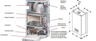
The difference from the gravity system is the need to install specific components. Some of them are necessarily used in a closed system, but are sometimes used in natural circulation. The source of thermal energy is boilers. Some of the wall-mounted gas, pellet, and solid fuel models are immediately equipped with the necessary safety group. If it is not available, it must be purchased separately and installed on the hot water pipe.
The sealed tank maintains pressure and compensates for the volume of coolant. Its efficient movement is ensured by a circulation pump, which is recommended to be installed on the return line near the boiler itself. This arrangement is dictated by the fact that the water in this place is quite cool, the device is less susceptible to overheating. The remaining elements are the same as in the gravitational system: pipelines, radiators or registers.
