Thermal elements of a heated floor do not come into contact with the air they heat, so the temperature in the room is controlled by an external device - a thermostat. The amount of electricity consumption depends on its functionality. Agree, for an informed purchase it is worth understanding the characteristics and capabilities of the device.
We will tell you how to buy the most suitable thermostat for your underfloor heating. The article we have presented describes its varieties, which differ in the type of control, the type of temperature-fixing device and the method of installation. Tips are provided to make it easier to choose the optimal model.
Manufacturers rating
Today, the choice of underfloor heating systems in stores is quite extensive.
In this regard, it can be difficult to choose from such a variety a truly high-quality product that meets all requirements. Therefore, it is necessary to consider the main manufacturers and compare the features of their products:
"Devi" is a manufacturer from Denmark that presents cable heated floors. This brand has an undeniable advantage: service stations are found in almost all large cities of our country, so if problems arise, you can always call a repair specialist who will help solve your problem. The warranty for underfloor heating from this manufacturer is 20 years, and the cost of their systems is often lower than that of competitors. Devi also produces high-quality thermostats, so many give the brand a well-deserved first place.
- Teplolux is a Russian manufacturer that became a leader in the domestic underfloor heating market in 2010. The manufacturer provides a 25-year guarantee, the price for this product is very reasonable, and the range is quite wide. Teplolux produces ultra-thin heated floors, mobile ones, and many others designed to create comfortable conditions.
- Energy is a British manufacturer that initially established itself in its homeland, and subsequently in other countries of the world. Its advantage over other manufacturers is the environmental friendliness of its materials. Also, Energy thermomats are considered one of the most economical both in terms of cable power consumption and the cost of the equipment itself. The manufacturer's warranty is 20 years.
- Nexans is a Norwegian company, famous all over the world, famous for its innovative developments. One of them is the connection of a thermomat without couplings, which allows you to adjust the temperature in different rooms without any problems.
- Legrand is a world-class specialist, engaged in the production of various electrical and information systems, including thermostats for heated floors. Its range includes all types: from simple mechanical to complex programmable regulators. The Celiane series is represented by high-tech programmable systems that will satisfy the most picky buyer.
Finally, about setting the temperature
To set up each floor heating thermostat and check the performance of the system as a whole, you should turn on the heating and set all devices to the desired temperature. Please note that the house needs to be warmed up completely. The optimal boiler operating mode is 60 °C; if the heat generator starts to “clock” (frequently switch off and start), it is better to reduce the power.
The essence of the setting is to select a comfortable temperature in all living areas. The thermostat display readings do not always correspond to our feelings, so the settings will have to be adjusted during operation. A separate issue is programming heating according to a schedule; this procedure is described in the instructions for a specific device.
Key Safety Points
Any electrical installation work must be carried out in strict accordance with safety precautions. Neglect of these provisions may result in the most unfavorable consequences. The key recommendations are:
- before starting work, turn off the power to the entire apartment/house or directly to the line allocated for connecting the thermostat, if such a possibility exists;
- Do not connect a disassembled device to the mains;
- do not use the regulator at temperatures above +40 and below -5;
- do not allow the thermostat to become dusty;
- Do not use any solvents to clean the device. The use of benzene for these purposes is also unacceptable;
- do not repair the regulator without the appropriate skills;
- do not exceed the power and current values specified in the manufacturer's instructions.
Description of the heating system
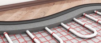
The most widespread today are warm electric floors, which can be installed with equal success in apartments in high-rise buildings or in private buildings. The use of modern technologies has made it possible not only to increase the efficiency of home heating, but also to significantly reduce utility bills.
The operating principle of such equipment is based on the property of semiconductors to emit heat when electricity passes through them. Accordingly, by decreasing or increasing the current intensity, you can effectively heat the room.
In the past, the most popular heating cables were those that ran under the floor and emitted heat as they passed through an electrical wire. Today, special infrared mats are considered advanced technology, which significantly reduce energy consumption, have high efficiency and are easy to install.
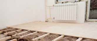
When connecting a heated floor yourself, you need to be careful, any mistake can lead to failures
Installation and connection of the thermostat
Before installation, carefully read the operating instructions for the device. Typically it contains the following installation instructions:
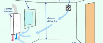
- thermostat height above floor level – 1.5…1.7 m;
- do not place the regulator with an air sensor near sources of heat or cold - heating radiators, air conditioners, ventilation openings;
- technological distance from window and door openings – 1 m (minimum);
- maintain the maximum distance between the thermostat and the distribution manifold of water transformer substations (the cable length is indicated in the instructions);
- the external sensor is located exactly in the middle between the underfloor heating loops at a distance of 500 mm from the wall;
- The floor temperature sensor is mounted inside the corrugated pipe; it should be easily pulled out after pouring the screed.
Surface-mounted devices are screwed directly to the wall, the wiring is laid in grooves. A recess is made under the built-in thermostats, and a regular socket box is installed.
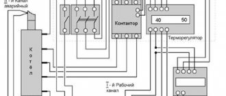
If the cable heating section consumes more power than the thermostat can switch, you need to use a modular contactor in the circuit. The specified actuator is mounted on a standard DIN rail.
Here the thermostat sends a control signal to the contactor, which opens the power line
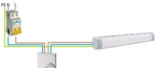
Some versions of thermostats have a contact for connecting a timer. This solution allows you to reduce the temperature in the room by 5 degrees once a day without purchasing an expensive digital model of the device. The timer circuit is shown below.
The Latin letter L in the diagram indicates the phase wire, N - zero (neutral)
Let's move on to water heated floors. The simplest way is to connect the thermostat to the servo drive directly (in series). Just first find out the type of drive, “normally open” must be connected to the normally open contact of the device, “normally closed” - to the break contact. Often, manufacturers put the appropriate markings on the terminals - NO or NC. The COM contact is common.
To implement multi-zone underfloor heating in a private home with wireless thermostats, use the following circuit diagram. Terminal numbers and other details are not indicated here, since equipment from different manufacturers has different markings.
Tips for choosing devices
When purchasing a thermostat, you need to know certain nuances in order to pay only for the necessary functions and ensure the longevity of the floor heating system and the device itself.
When choosing a thermostat, you should pay attention to the quality of the plastic case. If the manufacturer saves on this, then it is worth thinking about the reliability of internal components
These selection features include the following rules:
- For heating small rooms, an inexpensive mechanical or electronic thermostat with an internal air temperature sensor is suitable.
- It makes sense to buy a programmable thermostat if you need multi-zone temperature control, as well as to save energy when there are no residents at home during the daytime.
- The thermostat must correspond to the maximum power of the heating elements with a margin of 25-30% in case of operation at reduced voltage.
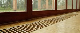
- For houses with wooden interior decoration, only overhead thermostat boxes are suitable.
Also, when choosing a device, it is necessary to take into account its design.
The existing model range allows you to buy not only reliable equipment, but also a thermostat that will fit perfectly into the interior of the room.
Some useful information about electrical wires
Inside the box you need to insert several wires with different insulation colors. According to the standards, zero is blue, and phase is black. The ground wire is painted in two colors - yellow and green.
To determine the phase, you should use an indicator screwdriver. In addition, at the time of preparation, before installing the floor heating regulator, you should check the voltage in the network. Ideally, it is as close to 220 volts as possible.
Next you will need to cut the main heating cable and the power cable. To do this, it is best to use a sharp knife or special nippers. You need to cut it so that the cables protrude from the mounting box by about 50 mm. Next, the wires are stripped.
If the model provides screwless cable fastening, then the stripping length is determined based on the recommendations indicated on the device body. Be careful not to let the stripped cables touch each other. It is best to connect the ground wire to the heating cable braid by soldering or a terminal.
After this, the power cable is connected to the mounted thermostat. Instructions on how to install a thermostat for a heated floor are indicated by the manufacturer either on the body or in the manual. The instructions may vary slightly between similar models, so the diagram must be studied in each individual case individually.
Connect the wire with the phase and secure it to the desired contact in the device; it is usually marked with the letter L. The terminal for the neutral wire is marked N. However, you should be careful, as there are types of systems in which the N terminal is intended for connecting the main heating cable. This nuance needs to be studied separately with special care.
Types of heating cables:
- A two-core heating cable hides two current-carrying conductors under its protective insulation. This type of cable is considered more convenient than its single-core version, because it is connected to the thermostat only at one end. In such a cable there are 3 wires nearby, two of which are conductive and one is grounding.
- A single-core cable has only one conductive wire, usually white.
Trouble-shooting
If the heated floor does not work and does not heat up, one of the possible reasons for this is a malfunction of the temperature sensor. The problem may also be caused by improper installation of the device.
To understand why the floor does not heat up, you must first inspect the visually accessible structural elements and make sure that they are correctly connected to each other. If incorrect assembly occurs, correct installation is required.
If everything is connected properly or repeated correct connection does not produce results, the cause of malfunctions in the system is a breakdown of one of its elements, which may include a temperature sensor. To make sure it is working properly, you need to check the device with a multimeter in the manner described above. It is better not to use a light bulb or diode here. Even minor changes in resistance can cause a malfunction of a heated floor, and they cannot be identified using improvised means.
If the parameters obtained during measurements do not coincide with the passport ones, the sensors are changed. If the corrugation is installed correctly, this will not be difficult.
If the corrugation is installed correctly, replacing the sensor will be very simple
If the reason for incorrect operation is not the temperature sensor or incorrect connection, it is better to call a technician. The problem may be caused by a breakdown of the thermostat or heating element. It will be difficult to eliminate it yourself. There are many workshops in Moscow that will repair incorrectly working or broken heated floors. They also exist in the regions, although there are much fewer of them there.
Installation and connection of the thermostat
The thermostat is usually mounted into the wall, like a regular switch. A place is selected for it near the existing electrical wiring, for example, near an outlet. First, a recess is made in the wall, a thermostat mounting box is installed there, and the wires (phase and neutral) of the power supply and temperature sensor are connected to it. The next step is connecting the thermostat.
There are “sockets” located on the side of the thermostat. The wires of the network (220V), sensor and heating cable are supplied here.
General thermostat connection diagram
It is useful to know that the wires that are connected when installing the thermostat are color coded:
- white (black, brown) wire – L phase;
- blue wire – N zero;
- yellow-green wire - ground.
Connecting the heated floor to electricity is carried out in the following order:
- Network wires with a voltage of 220V are connected to “sockets” 1 and 2. Polarity is strictly observed: wire L (phase) is connected to contact 1, wire N (zero) is connected to contact 2.
- A heated floor heating cable is connected to contacts 3 and 4 according to the principle: 3 contact - wire N (zero), 4 contact - wire L (phase).
- The wires of the temperature sensor (usually built into the floor, that is, determining the temperature in the thickness of the floor) are connected to “sockets” 6 and 7. Polarity principles do not need to be observed here.
- Check the functionality of the thermostat. To do this, turn on the -220V power supply, set the minimum temperature on the device and turn on the heating element system (by turning the knob or pressing the button). After this, the heating mode is changed to maximum, that is, the thermostat is “programmed” to the highest temperature that is possible for it. The correct operation of the device will be indicated by a click, which will indicate that the heating circuit is closed.
Connection diagrams may vary slightly depending on the types and models of thermostats. Therefore, so that the user does not make a mistake, all contacts are usually marked on the device body.
When connecting the thermostat, follow the connection diagram shown on the device body
Small differences in connection are also dictated by the characteristics of underfloor heating cables. According to their structure and number of cores, they are divided into single-core and double-core. Accordingly, there are some nuances in their connection diagrams.
Connecting a two-core cable to the thermostat
A two-core heating cable has two current-carrying conductors under a protective sheath. This type of cable is more convenient than a single-core design, since it is connected to the thermostat only from one end. Let's look at a typical connection diagram:
Connection diagram of a two-core cable to a thermostat
We see that in one two-core cable there are 3 wires adjacent: 2 of them are current-carrying (brown and blue), 1 is grounding (yellow-green). The brown wire (phase) is connected to pin 3, the blue wire (zero) is connected to pin 4, and the green wire (ground) is connected to pin 5.
The thermostat kit, the circuit of which we just looked at, does not include a grounding terminal. If there is a grounding terminal, installation is much simpler.
Two light green wires are connected to the ground loop through the PE terminal
Connecting a single-core cable
A single-core cable has only one current-carrying conductor, usually white. The second wire - green - is the grounding of the PE screen. The connection diagram could be like this:
Connection diagram of a single-core cable to a thermostat
White wires (both ends of a single-core cable) are connected to thermostat contacts 3 and 4, and a green ground wire is connected to contact 5.
Thermostatic valve
The device regulates the temperature of the coolant in the “return”. In practice, two options are used for connecting an ETP through a thermostatic valve.
First scheme
Boiler → Circuit → Thermostatic valve → Boiler
In practice it looks like this:
| °C | |
| Coolant at the outlet of the boiler | 60 |
| Thermal head reading | 20 |
| Average temperature reached | 30–35 |
At the entrance to the circuit, the water is too hot, and at the exit it has cooled noticeably. Depending on the thickness of the screed, the type of floor covering and the pitch of the pipe, the floor surface warms up differently. The required parameters are achieved only in the center. It takes a long time for water to cool from 60 to 20 degrees because the water speed is low. Connection via a thermostatic valve is suitable only for small areas - a bathroom, a corridor.
Second scheme
Radiator → Circuit → Thermostatic valve → Boiler
| °C | |
| Coolant at the outlet of the radiator | 45 |
| Thermal head reading | 25 |
| Average temperature reached | 30–35 |
Advantages of connecting an ETP after the radiator:
- Smaller temperature difference between inlet and outlet.
- High speed of water movement.
- Uniform heating of the floor.
Regulatory restrictions and dependence on radiators remain. In the case of a bathroom, such heating can be connected through a heated towel rail.
Manual adjustment of TP collectors
The simplest, although time-consuming, setting method is to adjust the temperature of the heated floor using manual valves. The task is somewhat simplified by installing flow meters (rotameters) on the comb.
Flow meters simplify the dosage of the amount of circulating coolant (flow) in one separate circuit of the underfloor heating system. In the case of group temperature control throughout the collector, the rotameter can also be used to balance the flow of coolant (smoothing out the difference in hydraulic resistance) along loops of different lengths.
The main elements of a flow meter valve are:
- housing with shut-off and control valve. It is screwed into the corresponding technical hole of the manifold;
- a flask made of transparent plastic or glass with a printed scale;
- float indicator that allows you to visually control the flow of liquid through the rotameter.
Manual adjustment of the underfloor heating manifold is carried out by screwing/unscrewing manual valves or adjusting the throughput of flow meters.
The sequence of manually setting the temperature of a warm water floor
At the beginning of the adjustment operations, it is necessary to make sure that the pipelines of the TP system (secondary circuit) are completely filled with coolant and have no air pockets. They are filled following the main heating system (primary circuit). At this time, all shut-off and control valves on the collectors must be closed.
After opening the main valves for the supply and return of the distributors for heated floors, the shut-off devices on each of the loops are opened sequentially. Air is bled through Mayevsky valves or automatic comb air vents. It is recommended to fill the next branch only after the previous one has been completely filled and its air has been guaranteed.
Having completed filling the first loop, it is necessary to turn on the heat pump of the secondary heating circuit and circulate the coolant through its system. The efficiency of liquid circulation is checked with built-in or overhead thermometers. As a last resort, you can simply put your hands on the supply and return pipes at the same time - they should be warm, but with a slight difference in heating.
The filled first loop should be cut off from the collectors at both ends using local shut-off and control valves. Then, the above actions are carried out with the next loop.
After sequential filling of all heat pump circuits, their shut-off devices are opened and the heat pump is switched on to operating mode. The temperature of the warm water floor is adjusted through the supply of coolant to each of its branches. It is set by changing the liquid flow rate (with a valve or rotameter), and control is carried out by changing the temperature gradient between the supply and return flow. Ultimately, this difference for different circuits should be the same, within 5-15C. The longer the loop, the more intense the coolant will cool and the greater its consumption required.
To monitor the correct adjustment of a warm water floor, it is rational to use non-contact laser or contact electric thermometers. Their installation to measure the temperature of the supply and return pipes will help reduce the time to obtain the result of changing settings from several hours to 10-15 minutes.
Types of heated floors
Warm floors can be water or electric. In water heated floors, the heating element is pipes with hot water supplied from the heating system. The power source for electric floors is the same, however, they are distinguished by the heating elements used: cable or film.
The heating element can be:
- single or double core resistive heating cable;
- thermal mats;
- self-regulating cable;
- heating film (bimetallic or carbon);
- carbon rods.
Connecting a thermostat to an infrared heater
Since in many cases home heating is carried out using infrared heaters, a thermostat can be used here to save electricity. Just as in previous cases, when the device reaches a certain temperature in the room, it will break the circuit and turn off the heater.
If 1 heat source is used to heat the room, then connecting the thermostat to the infrared heater is as follows:
In large areas, 2 or more electric heaters are installed, then a parallel circuit is used:
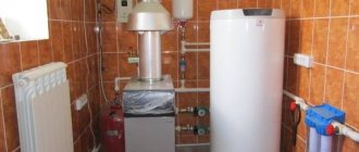
Owners heat small country houses, garages and other similar buildings using electric heating elements.
They are immersed in an oil or water medium that fills a homemade register welded from steel pipes. The simplest means of automation for such a heat source is the same thermostat; it is not difficult to install, you just need to lay the wires to the heater. Of course, it is easier to use heating elements with a built-in thermostat in the design, but then the control will again be indirect, based on the coolant. It is better to install a regular electronic unit with a sensor and connect it to the heating element. The figure below uses a simple diagram for connecting a heating element with a thermostat. Date: September 25, 2022
Three-way valve
The device is installed at the point with the highest temperature (on the supply pipe). The VTP connection diagram in practice looks like this:
Feed line
Boiler → 70 °C → Three-way mixer → Circulation pump → 45 °C → Warm floor
After the pump, a temperature sensor is installed on the supply pipe. It determines the degree of heating of the incoming water. Next comes the thermostatic valve.