The use of heat accumulators for the heating system allows optimizing the combustion of solid fuels in boilers. In simple words, if there is a buffer tank - a heat accumulator - the homeowner does not need to visit the boiler room often, and the firewood will burn in an optimal manner. But for this, the container needs to be selected correctly, and then connected to the heating equipment, which will certainly cause difficulties for an ignorant person. Therefore, it is worth understanding in detail what a heat accumulator for a solid fuel boiler is, how to select it and connect it to the heating of a private house.
Selection of quality equipment
The battery itself is selected for a pre-purchased solid fuel boiler and the parameters are calculated so that it can easily accumulate the maximum thermal energy that was generated by the direct source of the required heat.
The priority and main criterion for choosing a modern and well-thought-out heat accumulator will be the boiler itself, if its operating time of heat supply and power are somehow limited:
- To generate heat only a single one-time load of any fuel and its further analysis by the installed full heating system for a whole day.
- A solar type storage device of a certain power required for stable operation of the boiler, where heat is collected exclusively during daylight hours and in a stably uniform or exclusively peak use.
The main indicator for choosing a good heat accumulator is the consumer himself, when there is a need to cover the established thermal load for a certain period of time.
It is necessary to purchase this device in accordance with individual needs, as well as the characteristics of the installed solid fuel boiler.
Design in advance what kind of heat accumulator you need so that it can fully perform the functions and tasks assigned to it to enhance and control the thermal energy generated by the boiler.
When to bet
A heat generator is an expensive proposition.
Therefore, it is installed in the following cases:
- when there is a large area of the house;
- high consumption of hot water;
- when several types of heaters are used: a gas installation, or an electric boiler, or solar panels, which have come into fashion recently.
Heaters are combined, choosing what is best to use and at what time.
For example:
- during the day - solar panels, in the evening - boiler;
- During the day - a solid fuel boiler, at night - gas.
Prices for solid fuel boilers
solid fuel boiler
Multi-circuit heating systems with heat accumulators
Another undeniable advantage of the storage tank is the potential ability to operate it as a hydraulic gun.
This function is very necessary, since due to the fact that the tank body is equipped with at least four pipes, it becomes possible to select coolant with the desired temperature at one or another level of the storage tank. This will make it possible to equip a high-quality high-temperature circuit equipped with radiators, as well as heating with low temperatures, such as in a heated floor.
However, we should not forget about pumps that have heating control circuits, since the temperature at different levels of the storage tank at different times of the day is known to be different. At the same time, the function of the pipes is not limited to outlets for heating circuits. Several boiler systems equipped with different types can be connected to one heating accumulator.
Final stage
The last steps before starting operation will be:
- Cleaning, priming and painting the inside of the tank. It should be primed and painted several times.
- Afterwards, pre-prepared coils (heat exchangers) are connected.
- The tightness and reliability of the structure is checked. This is done using pressurized water.
- The outside of the tank is painted.
- Thermal insulation material is installed. The outer casing made of galvanized steel sheet is mounted on pre-prepared fastenings.
If it is possible to entrust this matter to professionals or buy a factory buffer tank, it is better to do so.
Since its independent production requires extensive experience in welding and skills in thermal and hydraulic engineering. In addition, this will require a lot of resources, effort and time. Date: September 25, 2022
Connection diagrams
There are many ways to connect a solid fuel boiler with a heat accumulator and a heating system. But they are all derived from the basic circuit shown below. With its help, it is easy to understand how these units work in pairs, and then install everything yourself.
A heat source running on solid fuel has a traditional boiler circuit with a mixing unit, whose task is to prevent the supply of cold coolant to the boiler. Then the supply and return pipelines are connected to the buffer tank, respectively, from above and below. In the same way, a heating system, also equipped with a mixing unit, is connected to the heat accumulator. Its purpose is to maintain the required water temperature in the system, adding part of the hot coolant if necessary.
Important point. The actual performance of the boiler circuit circulation pump should be slightly higher than that of the heating network pumping unit. Compliance with this condition will allow the flows inside the heat accumulator to move in the right direction (shown in the diagram with white arrows).
In fact, the network pump will be more powerful than the boiler pump and here's why. The resistance of the network of pipelines and radiators is higher than 3-5 m of pipe from the solid fuel boiler to the heat accumulator. The unit needs higher power and pressure to overcome this resistance. Therefore, a weaker boiler circuit pump can provide higher flow rates, you just need to configure both units correctly. There are 2 options to resolve the issue:
- When using 3-speed pumps, you can adjust their performance by switching speeds.
- Place a balancing valve at the inlet of the return from the system into the buffer tank, which can be used to make adjustments.
Simultaneous heating of heating devices and layer-by-layer loading of a heat accumulator is possible when the flows inside the tank move horizontally with a slight predominance from the side of the solid fuel boiler. The question arises - how to check this? The answer arises: thermometers must be installed at both return inlets to the tank (as in the diagram) and adjustments must be made by switching pump speeds or rotating the balancing valve
Important condition: the three-way valve of the heating network must be fully opened manually
By adjusting it is necessary to ensure that the temperature at the inlet to the heat accumulator (T1) is less than at its outlet (T2). This means that part of the hot water goes to “charging” the battery. You can learn more about all the points from an expert by watching the video:
Alternative scheme
This scheme for connecting a buffer tank and a solid fuel boiler was proposed by one of the participants in the popular forum. Its peculiarity is that in the event of a power outage, the operability of the circuit remains, although you have to pay for this with increased diameters of steel pipes. The figure below shows the connection of a heat accumulator to a closed heating system, but during installation it is better to make it open, as the author himself says.
Briefly, the essence is this: thanks to the T-shaped input on top of the tank, the radiators are simultaneously heated and the thermal accumulator, made by hand, is “charged”. The boiler circuit pump is controlled by a clip-on sensor on the supply line, turning on the unit when it reaches a temperature of 60 °C. The circulation in the network depends on the room thermostat to which the network pump is connected.
Note. The proposed strapping scheme was tested by its creator from his own experience. All details of its installation and operation are described by the author on the forum
Various types and piping schemes for solid fuel boilers
There are many ways to connect a boiler and related equipment to the overall heating system of a house. Let's look at the most common of them.
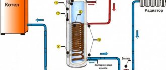
The storage tank acts as a hot water boiler
The design of the storage tank is a spiral located inside the heat accumulator. The hot coolant located inside heats the running water of the hot water supply circuit. In the event of a burnout and shutdown of the boiler, the heat accumulator allows maintaining an acceptable temperature in the room for up to 2 days. Provided that the DHW function is not used.
To control the flow and temperature of the coolant, an automatic thermal mixing device is used:
The device is also equipped with a check valve, an emergency automatic natural circulation valve (in case of a power outage), a built-in thermal fan and fitting.
The operating principle of the device is as follows. When the coolant reaches a certain temperature (780C), the thermal valve opens the water supply from the storage tank. The temperature is maintained at a given level by regulating the cross-section of the return passage from the central heating system to the bypass channel.
Connection diagram of a solid fuel boiler to a dual-purpose heat accumulator:
1. Security group; 2. Thermal storage tank; 3. Thermal mixer; 4. Membrane type expansion tank; 5. System make-up valve; 6. Heating system circulation pump; 7. Radiators; 8. Three-way mixing valve; 9. Check valve; 10. Circulation pump for the DHW system.
Connecting a heat accumulator and a separate DHW boiler
The volume of the passive heating boiler of the DHW system depends on the number of consumers and the power of the equipment used. When piping pellet boilers, it is not recommended to use polypropylene materials and structures. The outlet temperature of the heat exchanger at peak loads often exceeds the operating parameters of pipes made of polymer materials.
Connecting a solid fuel boiler with a separate hot water boiler:
1. Boiler. 2. Group 3. safety. 4. Diaphragm expansion tank. 5. 6. Pump. 7. Three-way mixing valve. 8. System make-up valve. 9. Radiator. 10. Indirect heating DHW boiler. 11. Thermal storage tank.
Parallel connection of two heating boilers
In order to extend the service life and evenly distribute the resources used, users often connect two different types of heating sources into a single heat supply scheme. In this case, the main source of heat in winter is a solid fuel boiler. The electric boiler is turned on in emergency mode and in the summer months, when it is used to heat water.
Wiring diagram for a solid fuel heating boiler with a parallel electrical connection:
1. Pellet boiler. 2. Heating system safety group. 3. Alternative boiler (electric or gas). 4. Separator to remove air from the system. 5. Circulation pump. 6. Manual three-way mixing valve. 7. Dry running protection valve. 8. Expansion tank. 9. System water supply valve. 10. Heat accumulator. 11. Washbasin. 12. 13. DHW pump.
A heating system based on a pellet boiler is quite complex and requires careful configuration. Before performing installation work, carefully read the instructions provided by the manufacturing companies.
Heat accumulator calculation
A container for storing thermal energy can be either purchased ready-made or made independently. But a logical question arises: how big should the tank be? After all, a small tank will not give the desired effect, and too large will cost a pretty penny. The answer to this question will help you find the calculation of the heat accumulator, but first you need to determine the initial parameters for the calculations:
- heat loss of the house or its square footage;
- duration of inactivity of the main heat source.
Let us determine the capacity of the storage tank using the example of a standard house with an area of 100 m2, which requires an amount of heat of 10 kW to heat. Let’s assume that the boiler’s net downtime is 6 hours, and the average coolant temperature in the system is 60 °C. Logically, during the period of time while the heating unit is inactive, the battery should supply 10 kW to the system every hour, for a total of 10 x 6 = 60 kW. This is the amount of energy that should be accumulated.
Since the temperature in the tank should be as high as possible, for calculations we will take a value of 90 ° C; household boilers are still incapable of anything more. The required capacity of a heat accumulator, expressed in mass of water, is calculated as follows:
- Q is the amount of accumulated thermal energy, for us it is 60 kW;
- 0.0012 kW / kg ºС is the specific heat capacity of water, in more conventional units of measurement - 4.187 kJ / kg ºС;
- Δt – difference between the maximum temperature of the coolant in the tank and the heating system, ºС.
So, the water accumulator should hold 60 / 0.0012 (90 – 60) = 1667 kg of water, which is approximately 1.7 m3 in volume. But there is one point: the calculation is made at the lowest temperature outside, which happens infrequently, excluding the northern regions. In addition, after 6 hours, the water in the tank will only cool down to 60 ºС, which means that in the absence of cold weather, the battery can be “discharged” further until the temperature drops to 40 ºС. Hence the conclusion: for a house with an area of 100 m2, a storage tank with a volume of 1.5 m3 will be enough if the boiler is inactive for 6 hours.
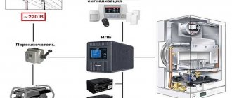
Requirements for uninterruptible power supply
To find out which uninterrupted unit is suitable for a gas boiler, you need to determine in advance the requirements for the device. It will help to become familiar with the main indicators of a UPS that characterize the efficiency of its operation. Some of them:
- Active and apparent (including the reactive component) power, defined as the product of the supply voltage and the current in the load.
- Harmonic distortion coefficient, indicating the quality of the output voltage - the deviation of the sinusoid shape from the ideal form.
- The presence of an external battery allows the boiler to continue operating during a complete absence of mains power for several hours.
- Duration of operation in offline mode.
- Limits of permissible input voltage fluctuations in Volts.
The battery life depends to a large extent on its capacity.
When the operating conditions of the boiler equipment require long interruptions in the power supply, the possibility of connecting additional batteries should be provided. It is also desirable that the purchased device has the function of automatically monitoring the state of the electrical network and restoring normal power supply.
Operating principle of the device
Each heating device has its own special principle of operation.
Some boilers are characterized by a uniform operating mode (gas and electric heating equipment), others, on the contrary, are characterized by an unstable process. The heating intensity depends on the method of fuel supply and the presence of devices that control the combustion process. With appliances running on natural gas or electricity, everything is simple and clear. To regulate the heating temperature of the coolant, it is enough to reduce or even stop the gas supply and turn off the power supply. Constant power supply ensures uninterrupted operation of boiler equipment. Both day and night, the boiler operates in automatic mode, independently regulating the heating temperature of the coolant. Solid fuel boilers are units with high inertia. The fuel placed in the firebox burns constantly, and it is physically impossible to quickly stop this process. The thermal energy obtained during the combustion process should not be wasted. Excess heat is accumulated along with the coolant in a special container, which acts as a thermal energy accumulator.
The situation is similar with a decrease in the intensity of boiler operation. When the fuel mass is burned, the boiler sharply loses its performance, and the boiler water in the heating circuit begins to rapidly cool down. Without the next portion of fuel, there is a threat of a decrease in temperature in heated rooms. Of course there is a way out. A new supply of firewood or coal will solve the problem. Another question is how often you can carry out such a procedure, especially if the firebox is empty at night.
A solid fuel boiler connected to a buffer tank is a complex that can solve the problem of heating residential premises for you. Installing a buffer tank frees you from frequent and hard work of loading the combustion chamber of the heating device with another amount of firewood.
You can understand the principle of operation of a buffer tank using the example of a car battery. While the engine is turned on in the car, the electric current generator runs in parallel. The electricity generated by the generator is stored in the battery. When the main engines stop, the battery supplies the necessary energy back to the vehicle systems.
The buffer capacity works similarly. There is heat, the heat accumulator accumulates it, as soon as the heating installation stops producing heat, hot water from the storage tank is used to heat all heating systems.
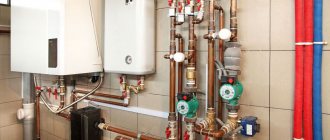
Connecting the heat accumulator to the heating system
As a general rule, the buffer tank is connected to the heating system in parallel to the heating boiler, therefore this circuit is also called a boiler piping circuit.
Let us present the usual diagram for connecting a heating unit to a heating system with a solid fuel heating boiler (to simplify the diagram, shut-off valves, automation and control devices and other equipment are not indicated on it).
Simplified wiring diagram for a heat accumulator
This diagram identifies the following elements:
- Heating boiler.
- Thermal accumulator.
- Heating devices (radiators).
- Circulation pump in the return line between the boiler and the heat exchanger.
- Circulation pump in the return line of the system between heating devices and heating equipment.
- Heat exchanger (coil) for hot water supply.
- Heat exchanger connected to an additional heat source.
One of the upper pipes of the tank (item 2) is connected to the boiler outlet (item 1), and the second is connected directly to the supply line of the heating system.
One of the lower pipes of the heat pump is connected to the boiler inlet, and a pump (item 4) is installed in the pipeline between them, ensuring the circulation of the working fluid in a circle from the boiler to the heat pump and vice versa.
The second lower pipe of the TA is connected to the return line of the heating system, in which a pump is also installed (item 5), which ensures the supply of heated coolant to the heating devices.
To ensure the functioning of the heating system in the event of a sudden power outage or circulation pumps failure, they are usually connected in parallel to the main line.
In systems with natural circulation of coolant, there are no circulation pumps (items 4 and 5). This significantly increases the inertia of the system, and at the same time makes it completely energy independent.
The heat exchanger for DHW (item 6) is located in the upper part of the heat exchanger.
The location of the additional heating heat exchanger (item 7) depends on the type of incoming heat source:
- for high-temperature sources (heating elements, gas or electric boiler) it is placed in the upper part of the buffer tank;
- for low-temperature ones (solar collector, heat pump) - in the lower part.
The heat exchangers indicated in the diagram are optional (items 6 and 7).
Types of hydraulic accumulators
These devices can be in vertical or horizontal configurations.
The operating principle of the devices is no different, except that vertical hydraulic accumulators with a volume of more than 50 liters have a special valve in the upper part for bleeding air, which gradually accumulates in the water supply system during operation. Air accumulates in the upper part of the device, therefore the location of the valve for bleeding is chosen in the upper part.
In horizontal devices for bleeding air, a special tap or drain is mounted, which is installed behind the hydraulic accumulator.
From small devices, regardless of whether they are vertical or horizontal, air is released by completely draining the water.
When choosing the shape of a hydraulic tank, proceed from the size of the technical room where they will be installed. It all depends on the dimensions of the device: whichever fits best into the space allocated for it will be installed, regardless of whether it is horizontal or vertical.
Principle of operation
The essence of the device’s operation in relation to boiler equipment does not differ significantly from the principle of protecting other electrical devices.
It is expressed in the adoption of special measures to stabilize the voltage and the ability to maintain it at the required level for some time. For these purposes, a UPS is used for boilers with a connected external battery, the direct voltage from which is converted into alternating voltage through an electronic inverter. To smooth out voltage fluctuations in the network or protect against its short-term loss, the principle of double conversion is used, consisting of the following:
- The corrected AC voltage is supplied to a line filter, which smoothes out sharp fluctuations by limiting RF harmonics.
- It enters the diode bridge, which converts the alternating component into a constant one.
- If necessary, part of the rectified current is spent on the charging circuit of the standby battery, used in a situation where the voltage disappears for a long time.
- The main part of it goes to the inverter, in which the reverse conversion of the constant component into variable is carried out.
- The stabilized voltage thus obtained is suitable for powering a solid fuel or gas boiler.
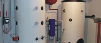
Advantages and disadvantages of buffer tank
Buffer tank for boiler
The main advantages of a heating system with a heat accumulator include:
- the maximum possible increase in the efficiency of the solid fuel boiler and the entire system while simultaneously saving energy resources;
- ensuring protection of the boiler and other equipment from overheating;
- ease of use of the boiler, allowing it to be loaded at any time;
- automation of boiler operation through the use of temperature sensors;
- the ability to connect several different heat sources to the heater (for example, two boilers of different types), ensuring their integration into one circuit of the heating system;
- ensuring stable temperature in all rooms of the house;
- the ability to provide domestic hot water without the use of additional water heating devices.
The disadvantages of heat accumulators for heating systems include:
- increased inertia of the system (from the moment the boiler is ignited until the system reaches operating mode, much more time passes);
- the need to install the heat exchanger near the heating boiler, for which a separate room of the required area is required in the house;
- large dimensions and weight, making it difficult to transport and install;
- the fairly high cost of industrially produced heat pumps (in some cases, its price, depending on the parameters, may exceed the cost of the boiler itself).
An interesting solution: a heat accumulator in the interior of the house.
In the interior
Installation 1st floor Attic Basement Section
The use of a heat accumulator is economically beneficial not only for solid fuel boilers, but also for electric or gas heating systems.
In the case of an electric boiler. The TA turns on at full power at night, when electricity tariffs are much lower. During the day, when the boiler is turned off, the premises are heated using the heat accumulated during the night.
For gas boilers, savings are achieved through the alternate use of the boiler itself and the heat exchanger. At the same time, the gas burner turns on much less frequently, which ensures lower gas consumption.
It is undesirable to install a heat accumulator in heating systems where rapid and or short-term heating of the room is required, since this will be hampered by the increased inertia of the system.
3 comments
Instead of the heat accumulators indicated in the article, storage water heaters with a capacity of 200 liters or more, connected in parallel, can be successfully used. Heat accumulators are connected to the heating boiler after normal heating of the house and (or) the threat of overheating of the boiler. This is much cheaper than the options offered. In addition, heating elements of water heaters can be used when the boiler is not operating, for example, at night. This is beneficial with a multi-tariff meter. The only thing is that when using ethylene or propylene glycol as a coolant, the magnesium rod installed to soften the water must be removed from water heaters. This system has been working for me for four years, allowing me to fire my solid fuel boiler once a day even in winter. In severe frosts (from -27) twice a day. The heat accumulator is served by three storage water heaters with a capacity of 200 liters each. Each water heater cost me 9700.
Popular models
It's time to understand the most popular models of heat accumulators for heating systems. We will consider products from domestic and foreign manufacturers.
Heat accumulator for heating boilers made in Russia Prometheus
The manufacturer of Prometheus heat accumulators is Novosibirsk. It produces models with volumes of 230, 300, 500, 750 and 1000 liters. The equipment warranty is 5 years. The heat accumulators are equipped with four outlets for connection to heating and heat sources. A layer of thermal insulation made of mineral wool is responsible for preserving the accumulated energy. The working pressure is 2 atm, the maximum is 6 atm. When purchasing equipment, take into account its dimensions - for example, the diameter of a 1000-liter model is 900 mm, which is why its body may not fit into standard doorways 80 cm wide.
The price of the presented heat accumulator for heating systems varies in the range from 65 to 70 thousand rubles.
SPSX-2G 1000
Another capacious heat accumulator for 1000 liters of water. It is equipped with one or two smooth-tube heat exchangers, but lacks thermal insulation, which must be taken into account when installing it - it will have to be purchased separately. The diameter of the case is 790 mm, but if thermal insulation is added to it, the diameter increases to 990 mm. The maximum temperature in the heating system is +110 degrees, in the DHW circuit – up to +95 degrees.
Buderus Logalux P 500-1000/5
These heat accumulators are available in modifications with six or ten connections. Temperature sensor terminals are also provided on board. The tank capacity is 960 liters, operating pressure is up to 3 bar. The thickness of the thermal insulation layer is 80 mm. The use of liquids other than water as a coolant is not allowed - this applies to both circuits, and not just the heating circuit. If necessary, it is possible to connect several heat accumulators in series into a single cascade.
Connection professional advice
In order to correctly and most efficiently implement a private heating system based on any solid fuel boiler, you can connect the heat accumulator using several methods. They are quite common among professional craftsmen, but you can learn this on your own, since there is nothing complicated or supernatural in these schemes.
Advice! Consider the fact that the cost of work directly depends on the basic principle of constructing a system for constant circulation of fuel in the boiler.
Heat accumulator connection diagram
With liquid mixing
The diagram for connecting a heat accumulator to a common type of solid fuel boiler is extremely clear. It is easily and accessiblely used in the piping of constant heating systems, which are based on the circulation of a simple gravitational type of fuel in the boiler. In this situation, this happens:
- When the set volume of water is heated in the heat exchanger of the device, its circulation begins throughout the entire installed pipeline system, which passes through the boiler valve.
- When the temperature set by the user is reached, the built-in valve actively begins to work and accordingly maintain the preset value, gradually mixing only cold water from the boiler itself.
- At this moment, hot water from the installed unit is poured into the tank - this is how the heat accumulator is charged.
- Over the entire period of time, which can only be determined by the boiler tank, the fuel is completely burned out.
- The reverse process begins, which consists of supplying water to small radiators. Temperature stability is maintained all the time.
- When the direct source of the required heat cannot maintain stable heating of water in the heat accumulator tank, the installed valve is quickly and reliably closed, and the system instantly returns to its original state.
If there is no power supply or the circulation pump fails, the boiler immediately goes into a special buffer mode, which allows the entire system to operate only on the check valve.
Connecting a heat accumulator to a solid fuel boiler
The collected water, which has been heated up to this point in the boiler itself, then actively flows into the installed tank. Then it goes to several heating radiators. This continuous process ensures that the water heats up smoothly and high temperatures drop gently.
Advice! In order for the heating circuit to function at its best, the heat accumulator must be mounted high enough so that there is no contact with the heating radiators.