A temperature sensor for a heating boiler is a device that controls the operation of the coolant. It analyzes the temperature regime and adjusts the temperature in the heating system. Thanks to the influence of the sensor, an optimal operating mode is established in the DHW system, allowing saving 25% - 30% of the energy consumed by the unit, and an emergency situation of the boiler equipment is also prevented. Today, almost any electric boiler is equipped with a temperature sensor.
Types of temperature sensors
The functioning of the meter depends on the voltage across the diode of the measuring circuit. The temperature change is directly proportional to the diode resistance. The lower the temperature, the lower the resistance, and vice versa.
In thermal power engineering, two types of diesel fuel are mainly used:
- Contact type, when direct contact of the measured medium with the sensor is ensured. For example, in a water or gas environment.
- The non-contact type measures not the temperature environment itself, but the level of heat or cold it generates by measuring the radiation that it emits.
In addition, DTs are divided according to the principle of operation into the following groups of sensors: electronic, electrical, mechanical and resistive. Additionally, DTs are distinguished by placement option:
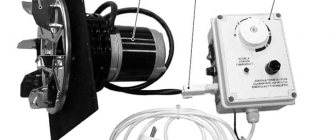
- overheads, which are mounted to ensure reliable contact on the surface with the medium being measured;
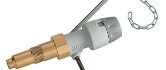
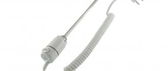
- submersible - located in the thickness of the medium with a measured temperature flow;
- room - air temperature sensor that controls the temperature of internal air in a heated room;
- external - measure the temperature of the external air behind the heated object.
By method of determining temperature
These include the simplest thermocouples, consisting of 2 dissimilar metals that generate electrical voltage in direct proportion to the change in temperature, and an RTD resistive temperature sensor.
This resistor changes its own electrical resistance, which is directly proportional to the change in temperature. Structurally, it is made of a coil with a thin wire wound from copper, platinum or nickel and a ceramic body.
Much less commonly used are manometric temperature sensors that measure the pressure of a gas or liquid medium in a closed vessel.
They are capable of measuring temperature using a non-magnetic method without using a current source, which allows them to be used for remote monitoring. Nevertheless, they have a sensitivity much less than other modifications of DT and have an inertia effect.
Contact sensors
This group of sensors in the boiler is responsible for monitoring the temperature of the heated water in order to prevent it from boiling above 100 C, which is why they are also called overheating sensors. When the limit temperature in the heating circuit is reached, the diesel engine releases the electrical contacts of the shut-off valve, which shuts off the gas supply to the boiler, after which it turns off.
This group of sensors includes special NTC immersion temperature sensors with a “positive temperature coefficient” that monitor the temperature inside the water circuit of a gas boiler. They operate on the basis of thermistors or biometric plates and are well compatible with vacuum sensors in the furnace.
Device and principle of operation
The principle of operation of the temperature sensor is based on measuring the parameters of resistance, pressure, emf or geometric dimensions of the working fluid from the boiler temperature. Only those physical quantities are selected that vary (linearly or nonlinearly) depending on the applied temperature and can be unambiguously converted into such. The required measurement accuracy is achieved by preliminary calibration of the element involved in a certain temperature range.
Thermal sensors have a fairly simple design in the form of the sensor itself in a housing with fasteners. It independently activates the contacts of the mechanical thermostat relay or, using the generated electrical signal, turns off the electric boiler/gas or solid fuel equipment upon reaching a certain temperature.
How to choose a temperature sensor
DT are the main elements of automatic safety and regulation of any boiler. Their selection is made by the manufacturer as part of the unit protection system. Nevertheless, there are situations when you need to do this yourself, for example, when reconstructing the heating supply circuit of a house or installing an additional indirect water heating boiler into the circuit.
The selection of a temperature sensor for a gas boiler is carried out taking into account the following indicators:
- The DT must be sensitive in operating temperature ranges and record all changes in the heated medium with the least delay, at high temperatures, for example, as in the furnace of a boiler;
- take into account the specifics of the controlled environment and technological features of installation: submerged or fixed to the body;
- take into account all negative influencing factors and, if possible, minimize them;
- take into account the design features of the DT: voltage, speed of the transmitting signal, permissible errors in measurements, areas of application, maximum service life, the need for periodic inspection and certification of the device.
At the same time, when choosing a diesel engine, you need to carefully read the instructions and connection diagram so that the requirements match the equipment already installed on the boiler.
As a rule, you should order meters recommended by the boiler manufacturer to ensure compatibility of safety system elements and guarantee their error-free operation. In cases where such modifications are not available in the retail chain, you should choose from certified analogues.
Where to install
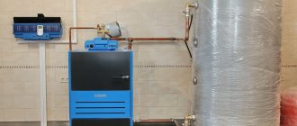
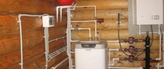
DT is set extremely close to the controlled parameter. So in double-circuit boilers they are placed on the return line before entering the boiler, at the outlet from it in the supply pipeline, at the outlet from the unit in the DHW circuit.
DT for monitoring the outgoing temperature of flue gases is installed at the outlet of the boiler in front of the mouth of the chimney. Wireless diesel engines for the boiler unit are placed directly on the controller or on the gas shut-off valve. Wired - connected by the option designated by the equipment manufacturer.
Temperature sensor connection
Boiler diesel engines are connected to a specific regulatory controller, which is responsible for the main temperature conditions of the unit and to a thermostat.
Room sensor
DT for determining the internal temperature in the room, in the system for regulating heating modes, is installed on the room wall under the following conditions:
- There should be no external sources of thermal energy or cooled air nearby, for example, from an air conditioner;
- free access of air flows to the temperature measurement point; no pieces of furniture or curtains should be installed next to the heat exchanger that could shield it from convective heat exchange in the room;
- DT is installed at a distance of at least 1.3 m from the floor level;
- There should be no EM radiation, electrical wiring or any powerful household electrical appliances in the operating area of the thermostat.
It is permissible to install the DT into a recess made in the wall, but it is important that the thermoelement is not closed at the top.
Connecting an external sensor
The sensor from outside the house is installed in the boiler’s weather-compensated automation circuit and is placed on the outside of the house. In order not to distort the actual readings of outside air temperatures, a number of conditions must be met when installing it:
- exclusion of direct exposure to UV rays on the measuring part of the diesel engine;
- contact with the wall should not be metallic;
- carefully consider the conditions for laying the DT cable, especially in places exposed to chemical and biological sources that can damage the cable insulation;
- the level of DT location on the wall must be no higher than 2/3 of the house, and if the building is three-story, then between the 2nd and 3rd floors;
- it is necessary to exclude all possible negative factors that reduce the sensitivity or accuracy of the sensor measurements, for example, the operation of a nearby air conditioner or fan with a high speed of air mass movement.
Connecting a sensor for a gas boiler
The temperature sensor operating in the gas boiler safety system is placed on the controller or on the valve from the gas network. When making an independent connection, first study the diagram presented by the manufacturer, select the installation location, marking and placement of the contact group.
Algorithm for connecting the sensor to a gas boiler on your own:
- I remove the front panel on the gas unit to open access to the board and contact group.
- I remove the jumper installed by the factory between the terminals.
- I connect the necessary wires from the DT contacts to these terminals with the polarity indicated in the diagram by the equipment manufacturer.
- When installing a wireless temperature sensor to a relay unit, I connect a 3-wire 220 V wire with a ground line.
Connecting the water temperature sensor
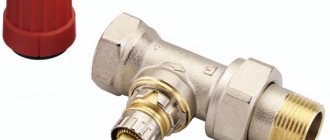
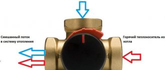
A temperature sensor for monitoring water heating in a double-circuit boiler is installed as a non-contact type, on the surface of the return pipe, while a contact sensor is inserted directly into the pipeline. In some cases, it is allowed to install a diesel engine on a circulation heating pump to prevent high-temperature return coolant from entering the boiler unit.
For a single-circuit unit, it is prohibited to install a temperature sensor in the return pipeline, so as not to block the circulation at a high return temperature, which will lead to an emergency shutdown of the boiler or underheating of distant rooms. In this case, it is recommended to install a diesel generator at the outlet of hot water from the boiler to prevent it from overheating when the boiler can be stopped in an emergency, for example, due to low vacuum in the furnace.
Sensor+thermostat
This scheme is energy efficient, since the boiler is controlled at two control points: the temperature of the heated water and the internal air in the room. This is especially important during transitional climatic seasons - spring and autumn, when rooms are warmed up not only from the heating system, but also from the sun's rays.
If the boiler operates only according to the temperature of the coolant, then the process of clocking the boiler will occur, when it will constantly turn on and off, which is very harmful for its internal components and especially for the burner.
When operating from a room thermostat, the indicators of which are more stable and change slowly, the operation of the boiler becomes more stable and brings real savings on heating up to 20%.
Main types of thermocouples for a gas boiler
There are many models of combustion front temperature sensors for gas equipment. There is even GOST R 8.585-2001 for thermocouples. They differ from each other in the length of the copper tube, the design and thickness of the hot junction head, and the method of fixing the contact pad on the AOGV block.
All models are available in standard lengths, from 30 to 150 cm in increments of 30 cm. The fitting nut can have an M8x1, M9x1, 11/32-inch thread or an M10x1 collet. For some AOGV models, a contact block-connector is used.
Thermocouples also differ in the alloys used.
| Thermocouple type | Spay | Marking according to GOST 6616-94 | Operating temperature ℃ |
| K | chromel-alumel | THA | up to 1300 |
| J | iron-constantan | TZHK | up to 1200 |
| N | nikhrosil-nisil | TNN | up to 1300 |
| R | platinum-rhodium-platinum | Chamber of Commerce and Industry13 | until 1700 |
| S | platinum-rhodium-platinum | TPP10 | until 1700 |
| B | platinumrhodium - platinumrhodium | TPR | until 1800 |
| T | copper-constantan | TMKn | up to 400 |
| E | chromel-constantan | THKn | up to 600 |
| U | copper-copper-nickel | THKn | up to 500 |
| L | chromel-copel | THC | up to 850 |
Four types of alloys are used for gas boiler control systems:
- type E is made by welding constant and chromel alloys. Operates at temperatures up to 740℃;
- type J is made on the basis of iron and constant. Operating temperature up to 600℃;
- type K has a junction made of aluminum and chromel. Works stably up to 1350 ℃ and has a fast response to temperature changes. For boilers operating on coal briquettes and gas fuel, it is not used due to high sensitivity to the increased content of CO, CO2;
- Type N works at temperatures up to 1200℃. Nichrosil and nisil are used in the junction. Has high accuracy. Used in high-power gas boilers.
In addition to thermocouples for non-ferrous metals, there are models based on a platinum-platinum-rhodium junction. They have high operational stability and low sensitivity to contamination by combustion products of gas and briquette fuels.
The cost of platinum thermocouples is an order of magnitude higher than chromium and iron ones, but temperature sensors on platinum-rhodium junctions are used mainly in industry. It makes no sense to try to install them on domestic gas boilers without shunting, since the operating voltage is almost twice the potential on the most common Chromel-Copel models.
Correct operation
When operating temperature sensors, the instructions of the boiler and measuring device manufacturer must be strictly followed. In order to ensure the accuracy of measurements, the sensitive element must have the greatest contact with the medium being measured; in addition, it will be necessary to promptly maintain the measuring device and calibrate it within the time limits indicated in the instructions.
Specifics of diesel engine operation in compliance with safety regulations:
- The diesel engine is installed in the environment that must be controlled and regulated by heat exchange;
- during installation, all negative factors that could change the sensor reading must be excluded;
- It is prohibited to operate the meter with damaged insulation;
- It is forbidden to disassemble the sensor yourself;
- All repair and maintenance operations are performed with the meter's networks completely disconnected from the 220V voltage.
Malfunctions
High-temperature operating conditions of the sensors, especially during unstable boiler operating conditions, lead to the fact that the primary meters fail. The boiler will often shut down if the thermocouple fails periodically, or diagnostics of the boiler operation will signal an error, and the instruments may show an “open circuit.”
Steps to troubleshoot a faulty temperature sensor:
- To repair the diesel engine, I check the correctness of the -ve and + ve conclusions
- I make sure that the cable is installed in accordance with the manufacturer's recommendations.
- I check that there are no external heat sources that could distort the DT readings.
- I check the temperature regulator setting.
- I diagnose possible interruption errors.
- I inspect the sensor for damage.
- I check the faulty thermocouple with a multimeter.
The temperature sensor is the main meter in the boiler safety and control system. It not only performs a protective function, but also contributes to up to 30% savings in thermal energy and gas consumption, since it does not allow overheating and boiler cycling.
Modern Russian requirements for the operation of household boilers oblige all boiler manufacturers to install diesel engines in the safety and protection system; it is better if this work is performed directly at the factory.
DIY repair
You can fix some problems yourself. The main thing is to follow our recommendations.
Water heater does not turn on
First of all, check if there is voltage in the network. You can check this with a screwdriver with an indicator: it should light up on “Phase”, but not on “Zero” and “Earth”. If the cable insulation is damaged, it is not recommended to carry out repairs. It is better to replace the element immediately, but make sure that the new cable matches the old one in terms of parameters.
A short circuit or lack of grounding leads to permanent shutdown of the RCD. A breakdown of the heating element on the body also leads to similar consequences. In this case, the element is diagnosed and replaced.
The RCD machine could break. To confirm your guesses, press RESET on the instrument panel. Is the light on? This means food is being served. Then press TEST and RESET again. If the indicator lights up again, the RCD is working normally.
Boiler does not heat water
Check the tightness of the contacts between the plug and the socket. If everything is in order and the voltage is supplied normally, you need to check the heating element. Do you have a storage type of boiler? Then drain the water from it first. A volume of water of 50-80 liters can be removed through the tap. It is better to drain 100 liters or more using a valve.
Remove the housing from the wall. Now you need to pull out the flange to which the heating element is attached. In Ariston 80 liter models, the flange is secured with only one bolt. In other cases, you will have to unscrew 5 bolts.
Disassembly is done like this:
- Rotate the flange along the axis.
- Take it out of the tank.
- Heater diagnostics are carried out with a multimeter. Read more in the article: “Replacing the heating element in a water heater.”
- If the multimeter needle moves, the part is working. Is it standing still? You need to install a new one.
Have you noticed that the water takes longer to heat up than usual? This does not mean that the heater is broken. Perhaps the reason is scale: over time it grows in a thick layer and interferes with normal heat transfer. Clean the element with special means.
Lack of heat may indicate a broken thermostat. Perform a reset on the boiler panel. If the appliance cannot be restarted, the thermostat is faulty.
A tester will help diagnose the breakdown more accurately:
- Set the multimeter to the maximum position.
- Attach the probes to the contacts of the thermostat (located next to the heating element).
- Does the arrow on the screen move? The device is working.
There is another option:
- Heat the thermostat with a lighter.
- Set the multimeter to "minimum".
- Place the probes on the contacts.
- If the arrow moves away from zero, then the part is functioning normally.
If there is a malfunction, the thermostat needs to be replaced. Disconnect the wiring from the part and pull it out of the hole.
Installation is carried out in reverse order.