How a smart plug works
“Communication” with a simple socket is carried out via SMS commands, so a SIM card is required for operation. The control unit contains a set of commands that are executed after receiving a code message. So, for example, most often an SMS command with code #01# turns on the socket, and with code #02# turns it off. To prevent strangers from interfering with this process, during initial activation, telephone numbers (usually no more than 5) from which commands will come are entered into memory using a special code. So, accidentally or specially sent commands from other numbers will not be executed by the socket. In addition, one of the numbers is designated as the main one, and all messages about changes in the state of the outlet are sent to it.
If you are not comfortable receiving SMS, you can control it by simply calling the device or installing a special mobile application. Unfortunately, not all sockets can be controlled via mobile applications yet, but this is becoming increasingly popular.
DIY instructions for connecting a gsm module to a boiler
Our country has been famous in all centuries for its own Kulibins. Connecting a modern module for a heating system is not difficult for them. Although manufacturers recommend doing this with the help of professionals. But the kit must include instructions for installing and servicing the modular system. Despite its small dimensions, this is a complex innovative system that requires a special approach during installation.
Self-installation will lead to the fact that the system simply cannot cope with the tasks assigned to it. But it’s quite possible to launch it yourself. To do this, just follow a few simple steps:
- install sensors and connect them to the module;
- Install a SIM card into your smartphone and enter the security code;
- install the SIM card into the module and repeat the code entry;
- Dial your phone number on the device.
Send the code from your phone to the module, after which all the necessary information will be sent to your smartphone.
What can a GSM socket be used for?
For example, to turn on some specific devices, say, to keep the refrigerator running. You can turn off the lights throughout the house while leaving them on. Naturally, the outlet to which the “smart” device and equipment are in turn connected must be connected to a separate machine. Or you need to be very careful to ensure that all other electrical appliances in the house are turned off after leaving. By leaving the refrigerator connected to the GSM device, in the event of a power outage, you will immediately receive an SMS notification and, perhaps, have time to save your food. The outlet itself is equipped with a spare power supply.
Another popular application: connecting to a heating system outlet. Before leaving for the dacha, you turn on the heating with one SMS message and arrive to a warm home. You can set the operation so that a certain temperature is maintained in the room, since the outlet is equipped with a corresponding sensor.
In the summer, you can connect an irrigation system to a smart outlet in the same way.
Most sockets on the market are compatible with all major household appliances: the maximum power of connected devices is limited to 3 kW, this is enough to connect even devices such as an electric kettle, air conditioner or oil radiator.
Remote control of the heating system
The Internet of Things (IoT, Internet of Things) is a promising area, as analysts say. One of the main IoT trends is home automation or, as marketers like to put it, the creation of a “smart home.” Let's leave the verbal exercises alone and consider a specific project.
Formulation of the problem
I live in my own house near Moscow.
In addition to the obvious advantages of this type of accommodation, there are some nuances. If in an apartment building most of the utility tasks are taken on by the management company, then in your own home you have to solve them yourself. One of these tasks for me was the need for remote monitoring and control of the heating system. It is a fair statement that in central Russia, heating in winter is not a matter of comfort, but of survival. According to a repeatedly proven empirical law, all troubles happen at the most inopportune times. After more than a decade of experience living in my own home, I also became convinced of the validity of this law.
But if, for example, the failure of a water supply pump in 30-degree frost can still be survived somehow, then the failure of a heating boiler turns into a disaster. In such frost, a normally insulated house gets cold in less than a day.
I often have to leave home for long periods of time, including in winter. Therefore, the ability to remotely monitor the condition of the heating system and its control has become an urgent task for me.
In my house, the heating system has two boilers, solar (alas, there is no gas and is not expected) and electric. This choice is due not only to issues of redundancy, but also to optimization of heating costs. At night, with the exception of severe frosts, the electric boiler works, since the house has a two-tariff electric meter. The power of this boiler is quite enough for a comfortable night temperature (18-19 degrees). During the day, the solar boiler comes into operation, raising the temperature to 22-23 degrees. The heating system has been operating in this mode for several years and allows us to conclude that this option is economical.
It is clear that daily manual switching of the operating modes of the heating system is not the most reasonable choice, so the decision was made to automate this process and, at the same time, provide the possibility of remote control.
Technical task
Following the developer’s habit, the first thing I did was systematize the requirements for the control system being created and wrote out something similar to a technical specification for myself.
Here is a short list of the main requirements for the designed solution:
- control the temperature in the house and outside
- provide three modes for selecting heating boilers (more details below)
- provide remote monitoring of the system status and its control
Initially, there were several more items on the list, but then they were excluded for various reasons.
For example, I planned to equip the system with a screen displaying current parameters and the ability to control via a touchscreen. But this seemed to me an unnecessary duplication of remote control via the Internet. Of course, you can come up with completely real-life situations when local indication and control are necessary. I don’t argue, but we shouldn’t forget that this possibility would require additional complexity and increased cost of the system. The heating system control algorithm includes an apocalypse scenario associated with a complete power outage. Of course, in this case there is no need to talk about remote control. But those in the house can switch to emergency heating mode with a few simple manipulations. It is enough to switch one external four-pole toggle switch and start the backup gasoline electric generator. This will ensure that the solar boiler operates autonomously. In practice, this has already happened a couple of times, when freezing rains led to massive breakdowns of power line wires.
Modern heating boilers, as a rule, have remote control units connected by a regular two-core wire. In order not to interfere with the factory control circuits, it was decided to switch these wires themselves. A break in the wire, carried out by a conventional electromechanical relay, leads to a stop in the operation of the boiler.
IoT Security Method
Having read horror stories about the consequences of hacking smart homes, I decided to play it safe and minimize the possibility of external hacking.
Someone will say, who needs to hack your smart home? I agree that the probability is minimal, but observing regular attempts to hack my web servers, I decided to act on the principle: it is better to sleep than to be underfed. Joke. To do this, I abandoned the common paradigm where a central server initiates control of distributed smart sensors (devices). It was decided to use a classic client-server scheme, where the client is a smart sensor. The choice of such an architecture is not always possible in IoT, but in this case it is quite acceptable, since heating systems have a fairly large inertia. Even the ability to instantly and arbitrarily change settings in the system, for example, the room temperature, does not lead to instantaneous achievement of the specified parameters.
Transferring the initiative in data exchange to the side of the smart sensor makes it possible to almost completely eliminate its hacking by unauthorized persons. After all, the sensor only receives a response from the server to its request. Theoretically, it is possible to intercept such a request and replace the response, but this threat is minimized, for example, by the https protocol. If there is no desire to raise this protocol in the sensor, then there is an option to calculate checksums taking into account parameters that are a priori unknown to the attacker. But this cryptographic issue is beyond the scope of the topic under consideration.
If the request does not receive a response from the server, the smart sensor, after waiting a certain timeout, continues to operate in the previously set mode.
As a server, it was decided to create a small website with a MySQL database, which was deployed on a third-level domain of one of my sites. The site was written using adaptive layout, which allows you to comfortably work from a smartphone. A five-minute period was selected for exchanging information with the server.
This choice is partly due to one nuance of the operation of the electric boiler. To prevent water from boiling in the heater bulb from the residual heat of the heating elements, the so-called boiler run-down is used. In other words, after the heating elements are turned off, the circular pump continues to work for some time. My boiler defaults to a 4-minute run-on time, although it can be increased to a longer time. Therefore, the five-minute exchange interval fit well into the logic of the heating system. And more frequent data exchange did not provide any benefit; it only led to an increase in the number of records in the server database.
Work algorithm
The operation of the smart sensor, called the weather module, does not contain anything unusual.
The cycle interrogates temperature and humidity sensors. This lasts approximately 4.5 minutes. Then a GET request is generated to the server and the received response is processed. As a result, the period (main cycle) is approximately 5 minutes long. Perfect accuracy is not required here; in practice, the period turned out to be several seconds shorter, which leads to a gradual shift. With an ideal five-minute period, 288 readings would be transmitted per day, but in reality it turns out to be 289-290. This does not affect the operation of the system at all. The main sketch of the program with detailed comments is given in the listing.
Due to the extensive amount of code, I did not publish implementations of the subroutines used. The listing contains diagnostic messages for output to the terminal. Main sketch of the program
/* * Sketch Meteo Control Mega2560 * ver. 13.0 * simplified automation algorithm: day - diesel, night - electric. Initial threshold is 21 degrees, step is 0.5 degrees * exchange with server via http 1.0 */ // libs #include #include “DHT.h” // wired connections // connecting the timer via the I2C bus, address on the bus 104 #define DS3231_I2C_ADDRESS 104 // define #define HYSTERESIS 0.5 // temperature threshold hysteresis, degrees #define LONG_CYCLE 9 // duration of the measurement cycle, 9 - about 5 minutes, taking into account the exchange time with the server #define SHORT_CYCLE 13 // duration of the small measurement cycle, 13 sec . taking into account the time of data collection from sensors, a small cycle turns out to be about 30 sec #define DAY_BEGIN 6 // start of the daily tariff period #define DAY_END 22 // end of the daily tariff period #define MIN_INTERVAL 3000 // temperature sensor reading interval 3 sec #define PIN_DHT_IN 23 / / input of temperature and humidity sensor inside AM2301 #define PIN_DHT_OUT 22 // input of temperature and humidity sensor outside AM2301 #define DHTTYPE DHT21 DHT dhtin(PIN_DHT_IN, DHTTYPE); DHT dhtout(PIN_DHT_OUT, DHTTYPE); #define RELAY_E 25 // control output of the electric boiler relay #define RELAY_D 24 // control output of the solar boiler relay #define LED_R 27 // LED RGB #define LED_G 29 // LED RGB #define LED_B 31 // LED RGB #define LED 13 / / internal LED #define LEAP_YEAR(_year) ((_year%4)==0) // to calculate leap year // vars uint32_t workTime; // boiler operating time from the moment the relay is turned on float hIn; // humidity inside float tIn; // temperature inside float hOut; // humidity outside float tOut; // outside temperature float tModule; // temperature inside the weather module float tInSet; // set temperature value inside float tOutSet; // set outside temperature value. Not used in the current version. The parameter is left for development byte seconds, minutes, hours, day, date, month, year; byte del; // large cycle counter, counts small cycles as decrement char weekDay[4]; byte tMSB, tLSB; float temp3231; static byte monthDays[] = {31, 28, 31, 30, 31, 30, 31, 31, 30, 31, 30, 31}; uint32_t unixSeconds; // UNIX timestamp uint16_t timeWorkElectro; // operating time (sec) of the electric boiler between exchange sessions with the server uint16_t timeWorkDiesel; // operating time (sec) of the solar boiler between exchange sessions with the server uint32_t unixSecondsStartCycle; // UNIX timestamp of the beginning of the cycle between communication sessions with the server int modeWork; // operating mode of the weather module, 0 - auto, 1 - manual-off, 2 - manual-electric, 3 - manual-diesel, 4 - semi-automatic-electric, 5 - semi-automatic-diesel byte typeBoiler; // type of working boiler, 0 - boilers are not working, 1 - electric, 2 - solar char statusBoiler; // status of a running boiler for the server char unit = '1'; // module id char mode; // label of the weather module operating mode for the server String message; // string to send to the server char ans; // character from the buffer String answerServer; // initial string of the server response String tInSer; // string from the server = internal temperature threshold String tOutSer; // string from the server = outside temperature threshold String timeSer; // string from the server = setting the time char datetime[15]; // array for setting the module time void setup() { Serial.begin(115200); // set the speed of the COM port for the terminal Serial.println("Start setup()"); Serial.println("Meteo Module. Ver.13.0 Unit Number: " + String(unit)); pinMode(LED, OUTPUT); //LED flash pinMode(LED_R, OUTPUT); //LED_R pinMode(LED_G, OUTPUT); //LED_G pinMode(LED_B, OUTPUT); //LED_B // initializing the external timer Wire.begin(); //set control register to output square wave on pin 3 at 1Hz Wire.beginTransmission(DS3231_I2C_ADDRESS); // 104 is DS3231 device address Wire.write(0x0E); Wire.write(B00000000); Wire.write(B10001000); Wire.endTransmission(); // set the default temperature threshold tInSet = 21; tOutSet = -15; // turn on the external thermometer pinMode(PIN_DHT_OUT, INPUT_PULLUP); dhtout.begin(); // enable the internal thermometer pinMode(PIN_DHT_IN, INPUT_PULLUP); dhtin.begin(); // set the boiler control pins to the output pinMode(RELAY_E, OUTPUT); pinMode(RELAY_D, OUTPUT); modeWork = 0; // automatic mode // boilers are turned off relayElectroSwitchOff(); relayDieselSwitchOff(); timeWorkElectro = 0; // reset the boiler operating time timeWorkDiesel = 0; unixSecondsStartCycle = 0; // reset the initial operating time of the boilers typeBoiler = 0; Serial.println("All Boilers Off"); digitalWrite(LED_G, HIGH); // turn on the green color of the RGB LED. Initial state, boilers are turned off //initialization serial 1 is to esp8266 Serial1.begin(115200); //baud rate to ESP8266 module Serial1.setTimeout(1000); while (!Serial1); String startcommand = "AT+CWMODE=1"; // ESP8266 module in client mode Serial1.println(startcommand); Serial.println(startcommand); delay(2000); del = 0; // reset the big loop counter } void loop() { Serial.print("Start loop()."); // diagnostic output of the current time get3231Date(); // get the current time unixSeconds = timeUnix(seconds, minutes, hours, date, month, year); // UNIX time stamp in seconds Serial.print("Current datetime: "); Serial.print(weekDay); Serial.print(", "); if (date < 10) Serial.print("0"); Serial.print(date, DEC); Serial.print("."); if (month < 10) Serial.print("0"); Serial.print(month, DEC); Serial.print("."); Serial.print(year, DEC); Serial.print(" - "); if (hours < 10) Serial.print("0"); Serial.print(hours, DEC); Serial.print(":"); if (minutes < 10) Serial.print("0"); Serial.print(minutes, DEC); Serial.print(":"); if (seconds < 10) Serial.print("0"); Serial.println(seconds, DEC); // collecting data from sensors Serial.println("Getting temperature and himidity"); getSensors(); // preparing a message to send to the server collectServerData(); // BLOCK OF EXCHANGE WITH THE SERVER AND INITIALIZATION // sending data to the server and receiving the control line Serial.println("Send data to server"); connectServer(); // analyzing the control string and setting new modes controlServer(); // BOILER CONTROL BLOCK DEPENDING ON THE SET MODE switch(modeWork){ case 0: // automatic mode Serial.println("Current Mode: Auto"); autoMode(); break; case 1: // manual mode Serial.println("Manual Mode"); manualMode1(); break; case 2: // manual mode Serial.println("Manual Mode"); manualMode2(); break; case 3: // manual mode Serial.println("Manual Mode"); manualMode3(); break; case 4: // semi-automatic mode Serial.println("Semi Auto Mode Electro"); semiAutoMode4(); break; case 5: // semi-automatic mode Serial.println("Semi Auto Mode Diesel"); semiAutoMode5(); break; } del = LONG_CYCLE; // set the long cycle counter while (del > 0) { Serial.print("Start short cycle #"); Serial.println(del); // display the small cycle number mDelay(SHORT_CYCLE); // collecting data from sensors Serial.println("Getting temperature and himidity"); getSensors(); del—; // decrement the counter in a large loop } } As I mentioned above, the weather module has three operating modes:
- auto
- semi-automatic
- manual
In automatic mode, the weather module uses the built-in real-time clock to select which boiler to turn on at one time or another.
During the hours of reduced electricity tariff, the electric boiler is started. The original version of the system provided for the possibility of operating the electric boiler during the daytime in order to save diesel fuel. In this version, the weather module monitored the duration of operation of the electric boiler during the day. If within an hour it was not possible to reach the set temperature in the house, the electric boiler was turned off and after a pause for a run-down, the solar boiler was switched on.
Based on the experience of the first winter, this option was removed. The reason was the insufficient power of the electric boiler, which could not ensure the achievement of the specified comfortable temperature in relatively severe frosts (below -10 degrees). Therefore, it was decided to unambiguously start the solar boiler during the day in automatic mode.
Semi-automatic mode implies a strict selection of one boiler or another while maintaining automatic adjustment of its operation based on the temperature sensors of the weather module. This mode has proven useful in several cases. Firstly, when one boiler fails, the operation of the other boiler is forced, regardless of the time of day. Secondly, in mild frosts and thaws you can turn on the electric boiler around the clock, or, conversely, in very severe frosts you can start only the solar boiler.
I almost never use manual mode. It involves not only choosing a specific boiler for operation, but also transferring control over it to a standard remote unit. In other words, the boiler will be controlled by the set temperature parameters on this unit. The weather module in this mode continues to work only as a temperature and humidity monitoring station.
In its request to the server, the weather module transmits a data packet that includes information about the current state of the boilers (which boiler is selected, whether it is working or not), the current local time of the weather module, the duration of operation of the boilers in the previous five-minute period, the current temperature and humidity inside and outside the house. The request also includes the weather module identifier. In my case this is unnecessary, but the habit of designing for scaling made itself felt.
After sending a request, the weather module waits for a server response within 20 seconds. The resulting response is parsed using regular expressions. The server response contains four parameters:
- threshold value of temperature inside the house
- threshold value of temperature outside the house
- specified operating mode
- initial setup time for the module's real-time clock
The current version does not use an outside temperature threshold.
This feature was provided to implement the choice of heating patterns, depending on the temperature “overboard”. Perhaps I will implement this function someday. The last parameter is required quite rarely. I only asked it twice. During initial startup of the module and after replacing the battery in the real-time clock module. If temporary settings do not require changes, then this parameter is zero.
After parsing the response from the server, the current boiler operating time counters are reset. After all, the previous value has already been sent to the server. When resetting, the pause time waiting for a response from the server is taken into account.
It should be noted that the transmitted boiler operating time has an estimated value. This parameter cannot be used to judge, say, the electricity consumed. This is due to the operating characteristics of heating boilers. For example, when the temperature in the boiler reaches 80 degrees, it turns off, but the circular pump continues to operate. When the coolant temperature drops to 60 degrees, the boiler starts working again. The weather module only measures the total time it took the boiler to reach the temperature threshold inside the house.
After reaching the set temperature, the boiler turns off, and the weather module continues to read temperature readings every 30 seconds. When the temperature drops by more than 0.5 degrees, the heating boiler comes back into operation. This hysteresis value was selected experimentally, taking into account the inertia of the heating system.
To visually indicate the functionality of the weather module, flashing of the built-in LED has been added to the delay subroutine between temperature measurement cycles.
I would like to note that the selection of the boiler operating mode occurs at the end of the five-minute period. When the module is initially turned on or when it is rebooted, the default mode is set to automatic.
Implementation
To implement the idea, I used what was at hand.
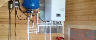
It was decided to build a weather module using Arduino modules. The Mega 2560, left over from previous experiments, was used as a processor board. This board is obviously redundant for this task, but it was available. In addition, it had a prototyping shield on which almost all other modules were located. These are the DS3231 real-time clock and the ESP8266(01) WiFi module. A switching unit with two relays was purchased for separate control of electric and solar boilers. The existing computer power supply was used as a power source. As you know, such a unit has a fairly wide selection of secondary supply voltage. There is +5V and, which is especially important when working with the ESP8266 WiFi module, +3.3V. In addition, these units are very reliable, taking into account the continuous nature of the weather module’s operation.
The figure shows the board switching diagram. The schematic diagram was not drawn due to its obviousness. There is an RGB LED in the figure for visual indication of the operating modes of the weather module. Green color indicates that the boilers are turned off, red means the solar boiler is running, and blue means the electric boiler is running. I didn't have 220 Ohm resistors on hand, so the RGB LED was connected directly to the board's outputs, without current-limiting resistors. I confess that I was wrong, but I took the risk consciously. The current consumption of each LED pin is only 20 mA, the board output allows you to connect up to 40 mA. In three years of operation there have been no problems so far.
DHT21 (AM2301) were used as temperature sensors. Initially, I used the DHT11 sensor to measure the temperature inside the house, but it has very poor measurement accuracy and, for an unknown reason, the DTH.h library did not work correctly when two different types of sensors were used in the circuit. But since the replacement of DHT11 due to its excessive error was obvious, I did not bother to deal with the library problem.
The numbers in the squares indicate the numbers of wires connecting external devices to the main board.
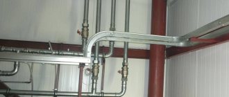
The entire circuit was assembled in a hanging metal panel used for installing electrical wiring. The choice of such a body was also related to what was at hand.
But here a completely predictable surprise awaited me. When the door was completely closed, the shield body shielded the WiFi signal. I had to leave the door ajar, since there was no desire to look for another suitable case and reinstall everything again. So I’ve been living with the door ajar for three years now.
Management server
The web server used for monitoring and management is written in pure PHP and has an adaptive layout.
Initially, there was an idea to write an application for Android, but I abandoned this idea, since a server would still be necessary. After authorization, several pages with information become available. This is the current state of the system according to the last request received from the weather module, a table of values in the current hour and a graphical representation of summary information for an arbitrary period of time. There is also a page with a choice of settings for controlling the weather module.
At the time of writing, the weather module was already turned off, because the heating season had ended. Therefore, all parameters on the main page of the site are relevant at the time of shutdown. The attentive reader will notice that this was May 2.
The values for January 25, 2018 are shown as an example of the graphs. Histograms show the operating time of the boilers.
Settings page
As I already mentioned, this solution for monitoring and controlling the heating system of a private home has already worked for three heating seasons. During this time, there were only two freezes caused by a long-term loss of the Internet channel. Moreover, not the entire weather module froze, but only the ESP8266 WiFi module.
In general, I am completely satisfied with the functionality of the system, but given the obvious redundancy of the platform used, I am thinking about expanding it.
Advantages of a smart plug:
- „Remote control via phone, smartphone or tablet.
- Ability to control ambient temperature.
- “Turning on and off devices according to a schedule.
- “Timely notification of power outages.
The simplest smart socket can perform such functions. At the same time, there are more complex options, for example, in the form of a surge protector with several output connectors (you can connect several electrical appliances). As a rule, there are options for 2, 3 or 4 outputs. They can be controlled simultaneously or separately.
Modern models can be connected to each other via radio or via the Internet, some are additionally equipped with a USB adapter. It connects to a router, which monitors commands coming either through a smartphone app or from a computer. The maximum distance for receiving a signal from the router is 30 m.
How to choose a gsm module: what you need to take into account
Before choosing a modular system for controlling a gas boiler, you need to study the models presented in the catalog and their technical characteristics.
Also consider several important parameters.
- A control method that can be carried out on the touch panel or via SMS. Many models already have software that allows you to quickly configure and manage.
- Complete set of the selected model. It is usually standard, but it is better to supplement the controller with additional options. This will allow you to control the level of gas pollution, possible leaks and even protect the house from vandals.
- Regulation channels. The more there are, the higher the functionality of the device, since it is possible to connect many additional functions.
- Microprocessor. The best models have weekly control programmers.
- High capacity battery that ensures continued operation in the event of a power outage.
Important! When choosing gsm modules for a heating boiler, you must take into account the recommendations of the heating system manufacturer.
If something is not clear, you can consult a professional directly on the site.
Using smart plugs in an apartment
Initially, a smart socket was created for the home: to control the operation of kettles, washing machines, water heaters and other household appliances. It is especially useful for “forgetful” citizens, so that they always and everywhere know for sure that the electrical appliance is turned off. Parents can “command” the computer in the children’s room from work, monitoring the time it turns on and off. Moreover, many smart
sockets allow you to connect additional sensors to a special connector: motion, door opening, smoke, gas leaks and others. And the additional output is for low-voltage equipment, for example, a siren. When the sensors are triggered, a notification will immediately be sent to the subscriber’s phone. In addition, the device will help reduce the amount of electricity consumed.
SIM card must be purchased separately. You can choose any mobile operator and any tariff. As a rule, you choose a tariff with expensive calls and cheap SMS messages, since the device only sends SMS messages. If someone uses a family tariff, then a GSM socket can be connected to it. Choose an operator available in your area. If cellular communication is poor and unreliable, install an additional antenna to strengthen the GSM signal.
Reviews of GSM boiler control modules: advantages and disadvantages
The innovative system causes various reviews about it. This is understandable, since nothing is perfect. And even such the latest equipment has both positive and negative sides. Most of the advantages have already been announced. It is worth pointing out the shortcomings. There aren't many of them.
Among the main users, the high cost of the devices is highlighted, although one can argue with this. The assortment includes a large number of inexpensive models that work no worse than their expensive counterparts.
Small but important modular systems for boiler control will help significantly reduce gas and electricity consumption. But, at the same time, they are able to create optimally comfortable living conditions even when a person is hundreds of kilometers from his own home.
Popular manufacturers and prices
The production of GSM modules is carried out not only by heating equipment manufacturers, but also by independent companies specializing directly in automation. Note that general automated systems are more flexible; they allow you to connect several devices in parallel. In other words, an excellent option for any heating boiler with the ability to connect, for example, a home security system.
"Xital" - boiler remote control system
Let's get acquainted with popular models of modules from the world's leading manufacturers. All of them have a standard set of functions.
Table No1. Review of popular models.
| Model | Manufacturer | Average market value |
| GSM-Climate | "Evan" | 7.5 thousand rubles. |
| GSM-12T | "Xital" | 8.4 thousand rubles. |
| GSM-8T | "Xital" | 8.2 thousand rubles. |
| GSM-4T | "Xital" | 7.7 thousand rubles. |
| GSM module, GSM thermometer | "Telemetrics" | 8.8 thousand rubles. |
| GSM module for Protherm heating devices | Protherm | 7.5 thousand rubles. |
| Buderus Logamatic Easycom | Buderus | 65 thousand rubles. |
| Vitocom 100 | Viessmann | 13.2 thousand rubles. |
| ZONT H-1 | Vaillant | 8.4 thousand rubles. |
On a note! Controlling heating remotely is rational and convenient. And the module described in the article allows you not only to monitor the operation of the entire system, but also to be aware of all faults, and also save a lot of money.
What are the dangers of high humidity in the house?
Excessively humid air harms furniture and interior items. Even premium quality wallpaper often changes color, becomes moldy, or peels off. The plaster can become completely damp, falling off in pieces. Simply put: expensive repairs will go down the drain.
Dampness even penetrates into closets and chests of drawers. Therefore, when humidity is high, items made of wood, leather and paper are the first to suffer. The worst thing about high humidity is that it creates a haven for mold and mildew. In a damp room, these microorganisms multiply quickly. Fungi and mold enter the human body with oxygen. Minimal harm from mold and fungi - runny nose and allergies. In the worst case, chronic diseases worsen. Both adults and children are at risk.